By Zhang Wei (Xieshi)
This long article discusses the implementation of the kernel. If you are not interested in this part, I suggest jumping directly to our solutions (after giving some thought to the three questions below).
Note: All the code in this article is Linux kernel source code, version 5.16.2.
Have you ever heard of a Virtual Local Area Network (VLAN)? It is used to isolate different broadcast domains in ethernet. It was born early. In 1995, IEEE published the 802.1Q standard [1], defining the format of VLAN in Ethernet data frames, which is still in use today. If you know VLAN, have you heard of MACVlan and IPVlan? With the emergence of container technology, IPVlan and MACVlan, as Linux virtual network devices, slowly came to the stage. IPVlan and MACVlan were introduced as network solutions for containers in the Docker Engine version 1.13.1 [2] in 2017.
Have you ever had the following questions?
- What is the relationship between VLAN, IPVlan, and MACVlan? Why is there a VLAN in their names?
- Why do IPVlan and MACVlan have various modes and flags, such as VEPA, Private, Passthrough? What are the differences?
- What are the advantages of IPVlan and MACVlan? Under what circumstances will users come across and use them?
These are the same problems I used to have, but today's article will explore the answers.
The following is background information. If you know Linux well, you can skip it.
In Linux, when we operate a network device, we will use nothing more than IP commands or ifconfig commands. In terms of the implementation of the IP command iproute2, it depends on the netlink message mechanism provided by Linux. The kernel will abstract a structure for each type of network device (real or virtual) that specifically responds to netlink messages. They are all implemented according to the rtnl_link_ops structure to respond to the creation, destruction, and modification of network devices (such as the intuitive Veth device):
static struct rtnl_link_ops veth_link_ops = {
    .kind   = DRV_NAME,
    .priv_size  = sizeof(struct veth_priv),
    .setup    = veth_setup,
    .validate = veth_validate,
    .newlink  = veth_newlink,
    .dellink  = veth_dellink,
    .policy   = veth_policy,
    .maxtype  = VETH_INFO_MAX,
    .get_link_net = veth_get_link_net,
    .get_num_tx_queues  = veth_get_num_queues,
    .get_num_rx_queues  = veth_get_num_queues,
};
The operation of Linux and the response of hardware devices require a set of specifications for a network device. Linux abstracts it as a net_device_ops structure. If you are interested in device drivers, you mainly deal with them. Let's take the Veth device as an example:
static const struct net_device_ops veth_netdev_ops = {
  .ndo_init            = veth_dev_init,
  .ndo_open            = veth_open,
  .ndo_stop            = veth_close,
  .ndo_start_xmit      = veth_xmit,
  .ndo_get_stats64     = veth_get_stats64,
  .ndo_set_rx_mode     = veth_set_multicast_list,
  .ndo_set_mac_address = eth_mac_addr,
#ifdef CONFIG_NET_POLL_CONTROLLER
  .ndo_poll_controller  = veth_poll_controller,
#endif
  .ndo_get_iflink   = veth_get_iflink,
  .ndo_fix_features = veth_fix_features,
  .ndo_set_features = veth_set_features,
  .ndo_features_check = passthru_features_check,
  .ndo_set_rx_headroom  = veth_set_rx_headroom,
  .ndo_bpf    = veth_xdp,
  .ndo_xdp_xmit   = veth_ndo_xdp_xmit,
  .ndo_get_peer_dev = veth_peer_dev,
};
From the definition above, we can see several semantically intuitive methods: ndo_start_xmit is used to send packets. Newlink is used to create a new device.
The data packet receiving of Linux is not completed by each process, in the process in which the ksoftirqd kernel thread first processes the receiving driver, Network Layer (ip, iptables), and transport layer (tcp, udp). Then, they're put into the recv buffer of the Socket held by the user process and processed by the kernel inotify user process. For virtual devices, all the differences are concentrated before the Network Layer, where there is a unified entrance, the __netif_receive_skb_core.
In the 802.1q protocol, a 32-bit domain is used to mark the VLAN field in the header of the Ethernet data frame. The structure is listed below:
| 16bits | 3bits | 1bit | 12bits |
| TPID is Protocol. | PCP is a Priority. | CFI is Format Identifier | VID is the VLAN ID. |
As shown above, there are 16 bits for marking Protocol, 3 bits for marking priority, 1 bit for marking format, and 12 bits for storing VLAN ID. You can easily calculate how many broadcast domains we can divide by VLAN. Yes, it is 212, which is 4,096. We minus the reserved all 0 and 1, and the customer divides 4094 available broadcast domains. (Before the rise of OpenFlow, the implementation of VPC in the earliest form of cloud computing relied on VLAN to distinguish networks. Due to this limitation, it was soon eliminated, which gave birth to another term you may be familiar with, VxLAN. Although the two are different, they still have something in common.)*
VLAN was originally a switch concept like bridge, and Linux implemented them in software. Linux uses a 16-bit vlan_proto field and a 16-bit vlan_tci field to implement 802.1q protocol in each Ethernet data frame. At the same time, for each VLAN, a sub-device will be virtualized to process the message after VLAN is removed. VLAN has its sub-device, namely a VLAN sub-interface. Different VLAN sub-devices send and receive physical messages through one master device. Is this concept a bit familiar? Yes, this is the principle of ENI-Trunking.
With the background knowledge, let's go deeper into the Linux kernel, starting with the VLAN sub-device. All the kernel code here is based on the new version 5.16.2.
VLAN sub-devices were not initially treated as separate virtual devices. After all, they appeared early, and the code distribution was messy. The core logic was under the /net/8021q/ path. From the background, we can understand that the netlink mechanism implements the entry for network interface controller device creation. For VLAN sub-devices, the structure of their netlink message implementation is vlan_link_ops, while the vlan_newlink method is responsible for creating VLAN sub-devices. The following is the kernel initialization code process:
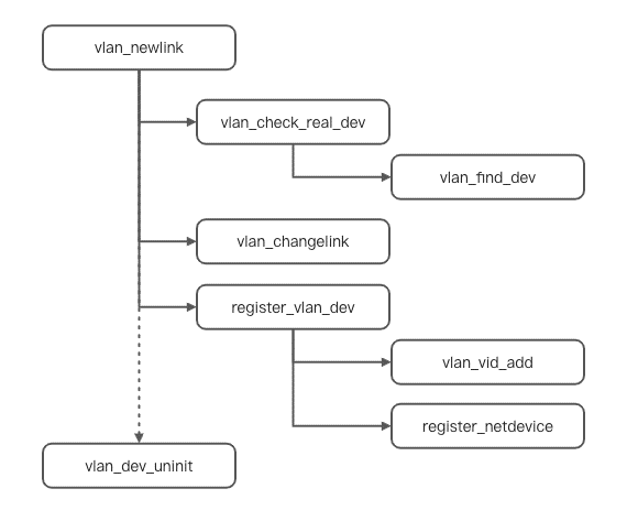
1. Create a Linux general net_device structure to save the configuration information of the device. After entering vlan_newlink, a vlan_check_real_dev will be carried out to check whether the incoming VLAN id is available. The Vlan_find_dev method will be called during the process. This method is used to find qualified sub-devices for a main device, which will be used later. Let's take a look at some codes intercepted in the process:
static int vlan_newlink(struct net *src_net, struct net_device *dev,
      struct nlattr *tb[], struct nlattr *data[],
      struct netlink_ext_ack *extack)
{
  struct vlan_dev_priv *vlan = vlan_dev_priv(dev);
  struct net_device *real_dev;
  unsigned int max_mtu;
  __be16 proto;
  int err;

  /*The part used for parameter verification is omitted here.*/

    // The vlan information of the vlan sub-device is set here, which is the default value of the protocol, vlanid, priority, and flag information related to the vlan in the background knowledge
  vlan->vlan_proto = proto;
  vlan->vlan_id  = nla_get_u16(data[IFLA_VLAN_ID]);
  vlan->real_dev   = real_dev;
  dev->priv_flags |= (real_dev->priv_flags & IFF_XMIT_DST_RELEASE);
  vlan->flags  = VLAN_FLAG_REORDER_HDR;

  err = vlan_check_real_dev(real_dev, vlan->vlan_proto, vlan->vlan_id,
          extack);
  if (err < 0)
    return err;

  /*There will be mtu configuration here*/

  err = vlan_changelink(dev, tb, data, extack);
  if (!err)
    err = register_vlan_dev(dev, extack);
  if (err)
    vlan_dev_uninit(dev);
  return err;
}
2. The next step is to set the properties of the device through the vlan_changelink method. If you have special configurations, the default value will be overwritten.
3. Enter the register_vlan_dev method, which is to load the previously completed information into the net_device structure and register it into the kernel according to the Linux device management unified interface.
From the perspective of the creation process, the difference between a VLAN sub-device and a general device is that the former can be found by the main device and the VLAN id in a vlan_find_dev way, which is important.
Next, let's look at the message-receiving process. According to the background knowledge, after the physical device receives the message and before entering the protocol stack processing, the conventional entry is __netif_receive_skb_core. We will analyze it from this entry. The following is the kernel operation process.
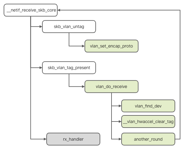
According to the diagram, we intercept __netif_receive_skb_core for analysis.
static int __netif_receive_skb_core(struct sk_buff **pskb, bool pfmemalloc,
            struct packet_type **ppt_prev)
{
  rx_handler_func_t *rx_handler;
  struct sk_buff *skb = *pskb;
  struct net_device *orig_dev;

another_round:
  skb->skb_iif = skb->dev->ifindex;
  /* This is an attempt to decapsulate the vlan of the data frame message itself and fill the two fields related to the vlan in the background.*/
  if (eth_type_vlan(skb->protocol)) {
    skb = skb_vlan_untag(skb);
    if (unlikely(!skb))
      goto out;
  }

    /* This is the packet capture point of tcpdump that you know well. Pt_prev records the handler of the previous packet processing. As you can see, a skb may be processed in many places, including pcap. */
  list_for_each_entry_rcu(ptype, &ptype_all, list) {
    if (pt_prev)
      ret = deliver_skb(skb, pt_prev, orig_dev);
    pt_prev = ptype;
  }

  /* In the case of vlan tag, if pt_prev exists, deliver_skb will be performed once. As such, other handlers will copy one, and the original message will not be modified. */
  if (skb_vlan_tag_present(skb)) {
    if (pt_prev) {
      ret = deliver_skb(skb, pt_prev, orig_dev);
      pt_prev = NULL;
    }
        /* This is the core part. We can see that after the vlan_do_receive processing, it will become a normal message again */
    if (vlan_do_receive(&skb))
      goto another_round;
    else if (unlikely(!skb))
      goto out;
  }

    /* This is where normal messages should arrive. Pt_prev indicates that the normal handler has been found. Then, call rx_handler to enter the upper-layer processing */
  rx_handler = rcu_dereference(skb->dev->rx_handler);
  if (rx_handler) {
    if (pt_prev) {
      ret = deliver_skb(skb, pt_prev, orig_dev);
      pt_prev = NULL;
    }
    switch (rx_handler(&skb)) {
    case RX_HANDLER_CONSUMED:
      ret = NET_RX_SUCCESS;
      goto out;
    case RX_HANDLER_ANOTHER:
      goto another_round;
    case RX_HANDLER_EXACT:
      deliver_exact = true;
      break;
    case RX_HANDLER_PASS:
      break;
    }
  }

  if (unlikely(skb_vlan_tag_present(skb)) && !netdev_uses_dsa(skb->dev)) {
check_vlan_id:
    if (skb_vlan_tag_get_id(skb)) {
    /* This is the case where the vlan id is not removed correctly, usually because the vlan id is invalid or does not exist locally
  }
}The entry point for data transmission of VLAN sub-devices is vlan_dev_hard_start_xmit. Compared with the packet-receiving process, the sending process is simpler. The kernel sends the following process.
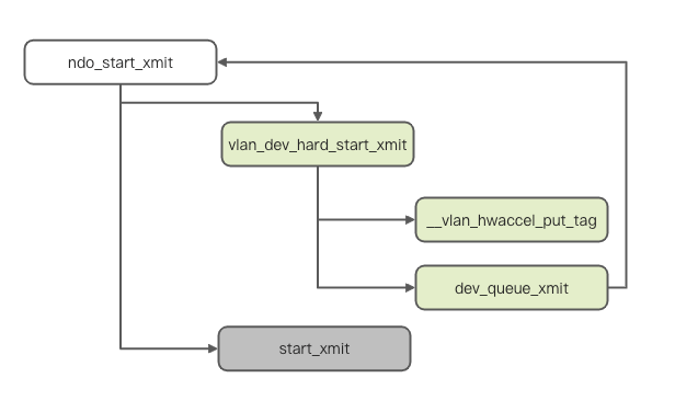
When the hardware is sent, the VLAN sub-device will enter the vlan_dev_hard_start_xmit method, which implements the ndo_start_xmit interface. It fills the VLAN-related Ethernet information into the message through the __vlan_hwaccel_put_tag method, modifies the device of the message as the main device, and calls the dev_queue_xmit method of the main device to re-enter the sending queue of the main device for sending. We intercept the key part to analyze.
static netdev_tx_t vlan_dev_hard_start_xmit(struct sk_buff *skb,
              struct net_device *dev)
{
  /* This is the filling of vlan_tci mentioned above. This information belongs to the sub-device itself. */
  if (veth->h_vlan_proto != vlan->vlan_proto ||
      vlan->flags & VLAN_FLAG_REORDER_HDR) {
    u16 vlan_tci;
    vlan_tci = vlan->vlan_id;
    vlan_tci |= vlan_dev_get_egress_qos_mask(dev, skb->priority);
    __vlan_hwaccel_put_tag(skb, vlan->vlan_proto, vlan_tci);
  }

    /* The device is directly changed from a sub-device to a master device. */
  skb->dev = vlan->real_dev;
  len = skb->len;
  if (unlikely(netpoll_tx_running(dev)))
    return vlan_netpoll_send_skb(vlan, skb);

    /* Here, you can directly call the master device to send messages */
  ret = dev_queue_xmit(skb);

    ...

  return ret;
}After the VLAN sub-devices, analyze the MACVlan immediately. The difference between MACVlan and VLAN sub-devices is that the former is no longer the capability of Ethernet itself but a virtual network device with its own driver. It is first reflected in the independence of the driver code. The relevant codes of MACVlan are located in the /drivers/net/macvlan.c.
There are five modes for MACVlan devices. Besides the source mode, the other four modes appear earlier. The following are the definitions:
enum macvlan_mode {
  MACVLAN_MODE_PRIVATE = 1, /* don't talk to other macvlans */
  MACVLAN_MODE_VEPA    = 2, /* talk to other ports through ext bridge */
  MACVLAN_MODE_BRIDGE  = 4, /* talk to bridge ports directly */
  MACVLAN_MODE_PASSTHRU = 8,/* take over the underlying device */
  MACVLAN_MODE_SOURCE  = 16,/* use source MAC address list to assign */
};
Let's remember the behavior of these modes first. We will elaborate on the reasons later.
For a MACVlan device, its netlink response structure is macvlan_link_ops. We can find that the response method for creating a device is macvlan_newlink. Starting from the entry, the following is the overall process of creating a MACVlan device.
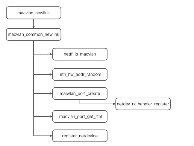
int macvlan_common_newlink(struct net *src_net, struct net_device *dev,
         struct nlattr *tb[], struct nlattr *data[],
         struct netlink_ext_ack *extack)
{
  ...

    /* Here, it checks whether the main device is a macvlan device. If so, use the main device directly.*/
  if (netif_is_macvlan(lowerdev))
    lowerdev = macvlan_dev_real_dev(lowerdev);

    /* A random mac address is generated here.*/
  if (!tb[IFLA_ADDRESS])
    eth_hw_addr_random(dev);

  /* The initialization operation is performed here, which means the rx_handler is replaced.*/
  if (!netif_is_macvlan_port(lowerdev)) {
    err = macvlan_port_create(lowerdev);
    if (err < 0)
      return err;
    create = true;
  }
  port = macvlan_port_get_rtnl(lowerdev);

    /* The next large paragraph is omitted about the mode setting.*/
  vlan->lowerdev = lowerdev;
  vlan->dev      = dev;
  vlan->port     = port;
  vlan->set_features = MACVLAN_FEATURES;
  vlan->mode     = MACVLAN_MODE_VEPA;

    /* Last, register the device */
  err = register_netdevice(dev);
  if (err < 0)
    goto destroy_macvlan_port;
}The message receiving of the MACVlan device still starts from the __netif_receive_skb_core entry. The following is the specific code process.
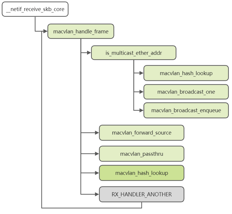
static struct macvlan_dev *macvlan_hash_lookup(const struct macvlan_port *port,
                 const unsigned char *addr)
{
  struct macvlan_dev *vlan;
  u32 idx = macvlan_eth_hash(addr);

  hlist_for_each_entry_rcu(vlan, &port->vlan_hash[idx], hlist,
         lockdep_rtnl_is_held()) {
    /* This logic of this part is that the macvlan searches the sub-device and compares the mac addresses.*/
    if (ether_addr_equal_64bits(vlan->dev->dev_addr, addr))
      return vlan;
  }
  return NULL;
}The sending process of MACVlan starts from the sub-device receiving the ndo_start_xmit callback function. Its entry is macvlan_start_xmit. The following is the overall kernel code process.
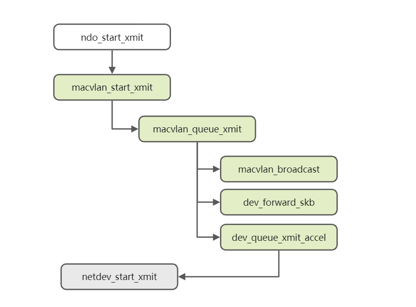
static int macvlan_queue_xmit(struct sk_buff *skb, struct net_device *dev)
{
  ...

  /* This is the logic in bridge mode. You need to consider the communication between different sub-devices.*/
  if (vlan->mode == MACVLAN_MODE_BRIDGE) {
    const struct ethhdr *eth = skb_eth_hdr(skb);

    /* send to other bridge ports directly */
    if (is_multicast_ether_addr(eth->h_dest)) {
      skb_reset_mac_header(skb);
      macvlan_broadcast(skb, port, dev, MACVLAN_MODE_BRIDGE);
      goto xmit_world;
    }
    /* This process directly forwards other sub-devices of the same master device.*/
    dest = macvlan_hash_lookup(port, eth->h_dest);
    if (dest && dest->mode == MACVLAN_MODE_BRIDGE) {
      /* send to lowerdev first for its network taps */
      dev_forward_skb(vlan->lowerdev, skb);

      return NET_XMIT_SUCCESS;
    }
  }
xmit_world:
  skb->dev = vlan->lowerdev;
    /* Here, the device of the message has been set as the master device and then sub-devices are sent through the master device. */
  return dev_queue_xmit_accel(skb,
            netdev_get_sb_channel(dev) ? dev : NULL);
}Compared with MACVlan and VLAN sub-devices, the model of IPVlan sub-devices is more complex. Unlike MACVlan, IPVlan defines the interworking behavior between sub-devices through flags. At the same time, three modes are provided. The following are the definitions:
/* At first, there was only I2 and I3. Later there was Linux and 13mdev, so 13s appeared accordingly. The main difference between them lies in the rx. */
enum ipvlan_mode {
  IPVLAN_MODE_L2 = 0,
  IPVLAN_MODE_L3,
  IPVLAN_MODE_L3S,
  IPVLAN_MODE_MAX
};

/* There is actually a bridge here. Since the default is bridge, all are omitted, and their semantics are the same as those of macvlan. */
#define IPVLAN_F_PRIVATE  0x01
#define IPVLAN_F_VEPA 0x02With the analysis of the previous two sub-devices, we can continue the analysis of IPVlan according to this idea. The netlink message processing structure of IPVlan devices is ipvlan_link_ops, and the entry method for creating devices is ipvlan_link_new. The following is the process of creating IPVlan sub-devices.
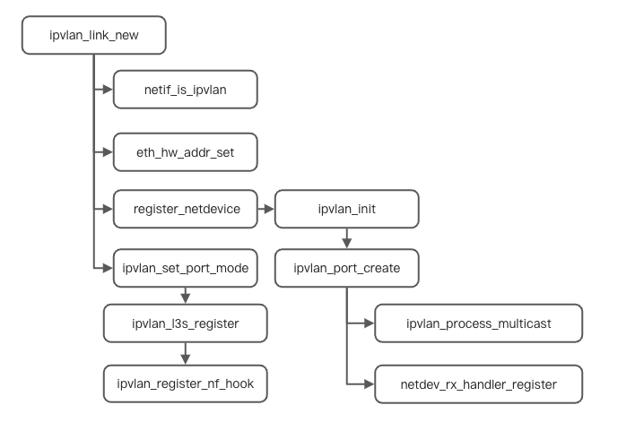
For the IPVlan network device, we intercept part of the ipvlan_port_create code for analysis:
static int ipvlan_port_create(struct net_device *dev)
{
    /* As you can see from here, port is the core of master device's management to sub-device.*/
  struct ipvl_port *port;
  int err, idx;

    /* Various attributes of the sub-device are reflected in the port. You can see that the default mode is l3.*/
  write_pnet(&port->pnet, dev_net(dev));
  port->dev = dev;
  port->mode = IPVLAN_MODE_L3;

    /* As can be seen here, for ipvlan, multicast messages are processed separately.*/
  skb_queue_head_init(&port->backlog);
  INIT_WORK(&port->wq, ipvlan_process_multicast);

    /* This is the regular operation. It relies on this to make the master device receive the package smoothly to cooperate with the ipvlan action. */
  err = netdev_rx_handler_register(dev, ipvlan_handle_frame, port);
  if (err)
    goto err;
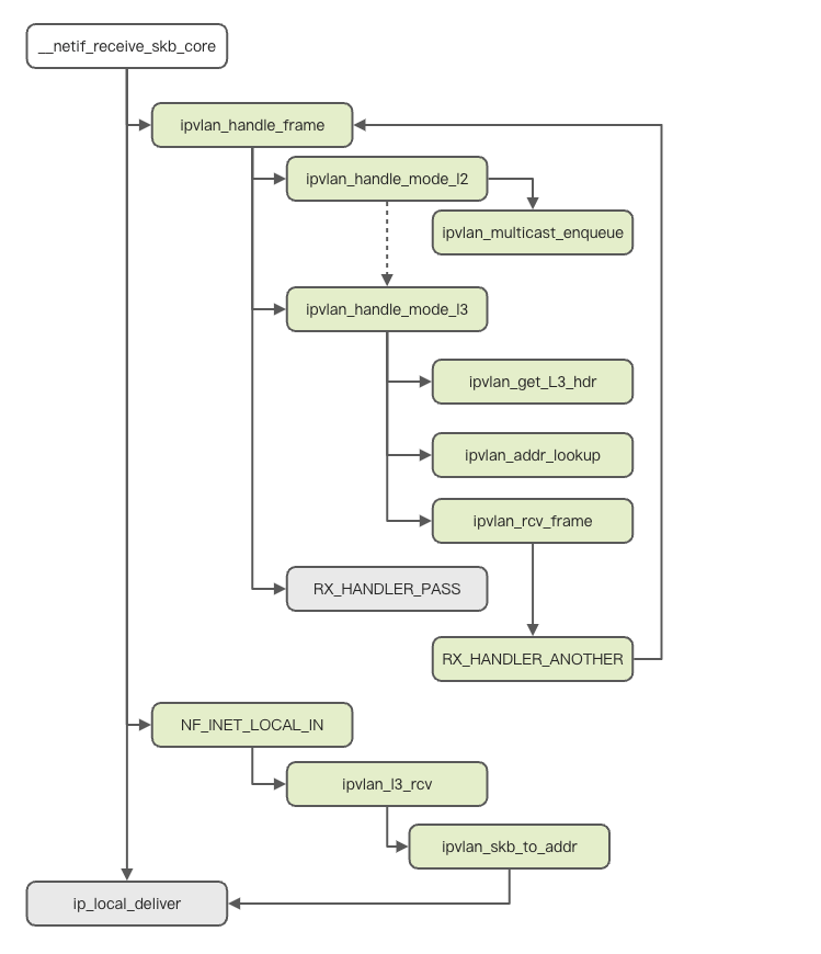
}The three modes of IPVlan sub-devices have different packet-receiving and processing processes. The following are the processes in the kernel.
Although the message sending of IPVlan is complicated in implementation, the fundamental reason is that each sub-device is trying to use the master device to send the message. When the IPVlan sub-device sends the packet, it enters the ipvlan_start_xmit, and its core sending operation is ipvlan_queue_xmit. The following is the kernel code process:
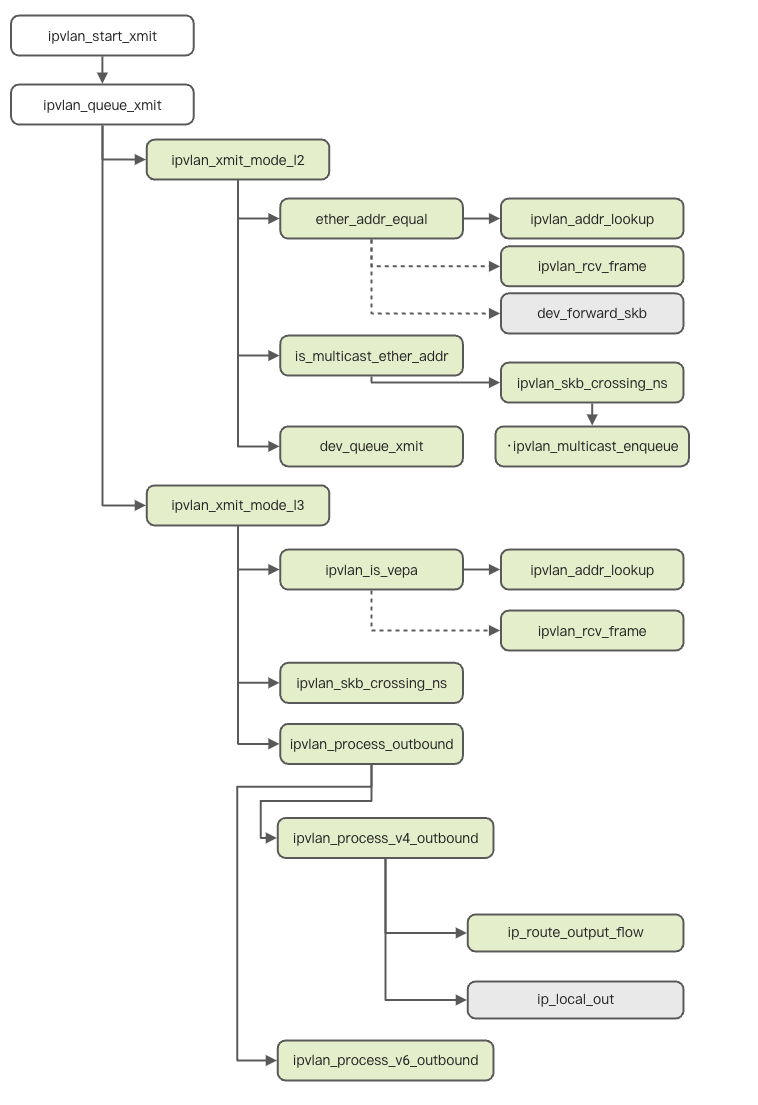
After the preceding analysis, the first question can be answered easily.
What is the relationship between VLAN, IPVlan, and MACVlan? Why is there a VLAN in their names?
It shows similarities in some aspects since they are called MACVlan and IPVlan. The overall analysis shows that the core logic of VLAN sub-devices is similar to MACVlan and IPVlan.
Therefore, it is not difficult to infer that the internal logic of MACVlan/IPVlan refers to the implementation of Linux VLAN to a large extent. Linux joined MACVlan on June 18, 2007, with the release of version 2.6.63 [3]. The description is listed below:
The new MACVlan driver allows the system administrator to create virtual interfaces mapped to and from specific MAC addresses.
IPVlan was introduced in version 3.19 [4] released on December 7, 2014. This is its description:
The new IPVlan driver enables the creation of virtual network devices for container interconnection. It is designed to work well with network namespaces. IPVlan is like the existing MACVlan driver, but it does its multiplexing at a higher level in the stack.
As for VLAN, it appeared much earlier than Linux version 2.4. The first version of drivers for many devices already supported VLAN. However, Linux's hwaccel implementation of VLAN was version 2.6.10 [5] in 2004. Among a large number of updated features at that time, this one appeared.
I was poking around in the National Semi 83820 driver noticed that the chip supports VLAN tag add/strip assist in hardware, but the driver wasn't making use of it. This patch adds the driver support to use the VLAN tag add/remove hardware and enables the drivers' use of the kernel VLAN hwaccel interface.
After Linux began to treat VLAN as an interface, there were two virtual interfaces, MACVlan and IPVlan. Linux virtualized different VLANs into devices to accelerate the processing of VLAN packets. In the later period, MACVlan and IPVlan made virtual devices useful under this idea.
As such, their relationship is more like a tribute.
Why do IPVlan and MACVlan have various modes and flags, such as VEPA, private, passthrough? What are the differences?
In fact, in the analysis of the kernel, we have roughly understood the performance of these modes. If the main device is a DingTalk group and all group friends can send messages to the outside world, several modes are intuitive.
Why are there these models? From the performance of the kernel, whether port or bridge is the concept of network, which means from the beginning, Linux is trying to show itself as a qualified network device. For the master device, Linux is trying to make it into a switch. For the sub-device, it is the device behind the network cable, which looks reasonable.
This is exactly the case. Whether it is VEPA or private, they were originally network concepts. It is not only Linux. We have seen many projects dedicated to disguising themselves as physical networks, all following these behavior patterns, such as OpenvSwitch [6].
What are the advantages of IPVlan and MACVlan? Under what circumstances will users come across and use them?
Here comes the original intention of this article. We found from the second question that both IPVlan and MACVlan are doing one thing: virtual networks. Why do we want a virtual network? There are many answers to this question. Like the value of cloud computing, virtual networks, as a basic technology of cloud computing, are ultimately aimed at improving resource utilization efficiency.
MACVlan and IPVlan serve this ultimate goal. The era when the rich ran a helloworld script with one physical machine has passed. From virtualization to containerization, the era puts forward higher requirements for network density. With the birth of container technology, Veth stepped onto the stage first, but with high enough density, efficient performance is still needed. MACVlan and IPVlan have emerged in a way to increase density and ensure efficiency through sub-devices (and our ENI-Trunking).
At this point, I would like to recommend a new high-performance and high-density network solution brought by Container Service for Kubernetes (ACK) - IPVlan solution [7].
ACK implements an IPVlan-based Kubernetes network solution based on the Terway addon. Terway is a network addon developed by ACK. Terway allows you to configure networks for pods by associating elastic network interfaces with the pods. Terway allows you to use standard Kubernetes network policies to regulate how containers communicate with each other. In addition, Terway is compatible with Calico network policies.
In the Terway network addon, each pod has its network stack and IP address. Pods on the same Elastic Compute Service instance communicate with each other by forwarding packets inside the ECS instance. Pods on different ECS instances communicate with each other through ENIs in the VPC in which the ECS instances are deployed. This improves communication efficiency since no tunneling technologies, such as Virtual Extensible Local Area Network (VxLAN), are required to encapsulate messages. The following figure shows the network type of Terway.
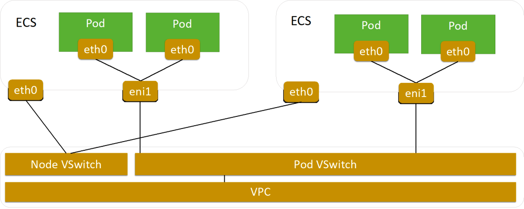
If users select the Terway network addon when they create a cluster, they can enable the Terway IPvlan mode. The Terway IPvlan mode provides high-performance networks for Pods and Services based on IPvlan virtualization and eBPF technologies.
Compared with the default Terway mode, the Terway IPvlan mode optimizes the performance of Pod networks, Service, and NetworkPolicy.
Therefore, allocating the IPvlan network interface controller with IPvlan to each service pod ensures the density of the network but also enables the Veth scheme of the traditional network to achieve a huge performance improvement (please see link 7 for details). At the same time, the Terway IPvlan mode provides a high-performance Service solution. Based on the eBPF technology, we circumvent the long-criticized Conntrack performance problem.
No matter what kind of business, ACK with IPVlan is a better choice.
Thank you for reading. Lastly, there is another question behind this question. Do you know why we chose IPVlan instead of MACVlan? If you know about virtual network technology, you will get the answer soon after reading what's mentioned above. You are welcome to leave a message below.
[1] About IEEE 802.1Q
https://zh.wikipedia.org/wiki/IEEE_802.1Q
[2] Docker Engine release notes
https://docs.docker.com/engine/release-notes/prior-releases/
[3] Merged for MACVlan 2.6.23
https://lwn.net/Articles/241915/
[4] MACVlan 3.19 Merge window part 2
https://lwn.net/Articles/626150/
[5] VLan 2.6.10-rc2 long-format changelog
https://lwn.net/Articles/111033/
[6] [ovs-dev] VEPA support in OVS
https://mail.openvswitch.org/pipermail/ovs-dev/2013-December/277994.html
[7] Use IPVlan to Accelerate Pod Networks in Alibaba Cloud Kubernetes Clusters
https://developer.aliyun.com/article/743689
An In-Depth Interpretation of the RocketMQ Storage Mechanism

508 posts | 49 followers
FollowAlibaba Cloud Native Community - March 6, 2023
Alibaba Cloud Native - June 12, 2023
OpenAnolis - October 26, 2022
Alibaba Developer - September 7, 2020
Alibaba Cloud Native - June 9, 2023
Alibaba Clouder - April 19, 2021

508 posts | 49 followers
Follow Alibaba Cloud Linux
Alibaba Cloud Linux is a free-to-use, native operating system that provides a stable, reliable, and high-performance environment for your applications.
Learn More Cloud-Native Applications Management Solution
Accelerate and secure the development, deployment, and management of containerized applications cost-effectively.
Learn More Container Service for Kubernetes
Alibaba Cloud Container Service for Kubernetes is a fully managed cloud container management service that supports native Kubernetes and integrates with other Alibaba Cloud products.
Learn More Networking Overview
Connect your business globally with our stable network anytime anywhere.
Learn MoreMore Posts by Alibaba Cloud Native Community