By Yujing

As data centers rapidly develop, high-performance networks continue to push the limits of bandwidth and latency. The bandwidth of network interface controllers (NIC) has grown from 10 Gb/s and 25 Gb/s in the past to 100 Gb/s and 200 Gb/s at present, and is expected to reach 400 Gb/s in the next generation. This growth rate exceeds that of the CPU. In order to meet the communication requirements of high-performance networks, Alibaba Cloud has not only developed high-performance user-mode protocol stacks (Luna and Solar), but has also utilized RDMA technology to fully leverage high-performance networks, particularly in the fields of storage and AI. Compared to the Socket interface provided by Kernel TCP, the abstraction of RDMA is more complex. In order to use RDMA more efficiently, it is essential to understand its working principles and mechanisms. This article uses the RDMA NIC of NVIDIA as an example to analyze its working principles and the interaction mechanism between software and hardware.
RDMA (Remote Direct Memory Access) is designed to solve the data processing latency on the server side during network transmission. It enables a system to quickly transmit data to another over the network without consuming any CPU. It eliminates the overhead of memory copy and context switch operations, thereby releasing memory bandwidth and CPU cycles for overall system performance improvement.
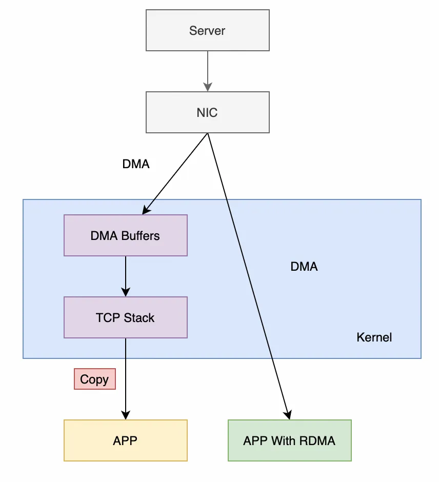
First, let’s look at the most common Kernel TCP. Its process of receiving data mainly goes through the following stages:
It can be seen that there are three context switches (an interrupt, user-mode and kernel-mode context switches) and one memory copy. Although the kernel has some optimization methods, such as reducing the number of interrupts through the NAPI mechanism, the latency and throughput of Kernel TCP still work poorly in high-performance scenarios.
After using the RDMA technology, the main process for receiving data changes to the following stages (taking send/recv as an example):
The above process has no context switch, no data copy, no processing logic of protocol stack (offloaded to the RDMA NIC), and no kernel involved. CPU can focus on data processing and business logic without spending a large amount of cycles to process protocol stacks and memory copies.
From the above analysis, we can see that RDMA is completely independent of traditional kernel protocol stacks. Therefore, its software architecture also varies from that of kernel protocol stacks, including the following parts:
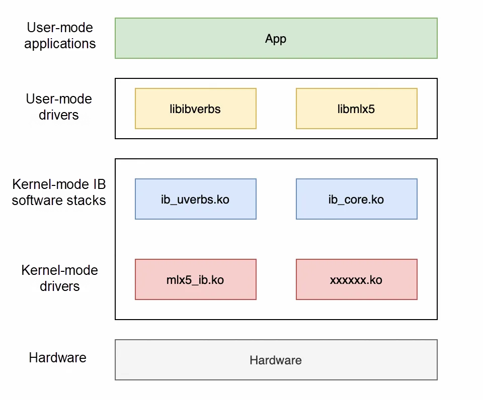
1. User-mode drivers (libibverbs, libmlx5, etc.): These libraries belong to the rdma-core project (https://github.com/linux-rdma/rdma-core). Various Verbs APIs are provided for users. In addition, there are also some specific APIs of manufacturers. The reason why this layer is called "user-mode drivers" is that RDMA directly interacts with hardware in the user mode. However, the traditional way of implementing HAL in the kernel mode does not meet the requirements of RDMA, so RDMA needs to be aware of hardware details in the user mode.
2. Kernel-mode IB software stacks: An abstraction layer of the kernel mode, providing a unified interface for applications. These interfaces can be called by both the user mode and the kernel mode.
3. Kernel-mode drivers: They are NIC drivers implemented by various manufacturers, and directly interact with hardware.
Since RDMA allows hardware to directly read and write the memory of the user-mode app, it causes many problems:
To address the above issues, RDMA introduces two concepts:
It may be abstract, so let's take a practical example to see how RDMA registers memory:
// Scan RDMA devices and select the device we want to use.
int num_devices = 0, i;
struct ibv_device ** device_list = ibv_get_device_list(&num_devices);
struct ibv_device *device = NULL;
for (i = 0; i < num_devices; ++i) {
    if (strcmp("mlx5_bond_0", ibv_get_device_name(device_list[i])) == 0) {
        device = device_list[i];
        break;
    }
}

// Open the device and generate a context.
struct ibv_context *ibv_ctx = ibv_open_device(device);

// Assign a PD.
struct ibv_pd* pd = ibv_alloc_pd(ibv_ctx);

// Allocate 8K memory and align it based on the page (4K).
void *alloc_region = NULL;
posix_memalign(&alloc_region, sysconf(_SC_PAGESIZE), 8192);

// Register the memory.
struct ibv_mr* reg_mr = ibv_reg_mr(pd, alloc_region, mr_len, IBV_ACCESS_LOCAL_WRITE);
Open the debug information of the kernel module:
echo "file mr.c +p" > /sys/kernel/debug/dynamic_debug/control
echo "file mem.c +p" > /sys/kernel/debug/dynamic_debug/control
Output logs:
infiniband mlx5_0: mlx5_ib_reg_user_mr:1300:(pid 100804): start 0xdb1000, virt_addr 0xdb1000, length 0x2000, access_flags 0x100007
infiniband mlx5_0: mr_umem_get:834:(pid 100804): npages 2, ncont 2, order 1, page_shift 12
infiniband mlx5_0: get_cache_mr:484:(pid 100804): order 2, cache index 0
infiniband mlx5_0: mlx5_ib_reg_user_mr:1369:(pid 100804): mkey 0xdd5d
infiniband mlx5_0: __mlx5_ib_populate_pas:158:(pid 100804): pas[0] 0x3e07a92003
infiniband mlx5_0: __mlx5_ib_populate_pas:158:(pid 100804): pas[1] 0x3e106a6003
Combined with the code analysis of the kernel module, memory registration can be roughly divided into the following stages:
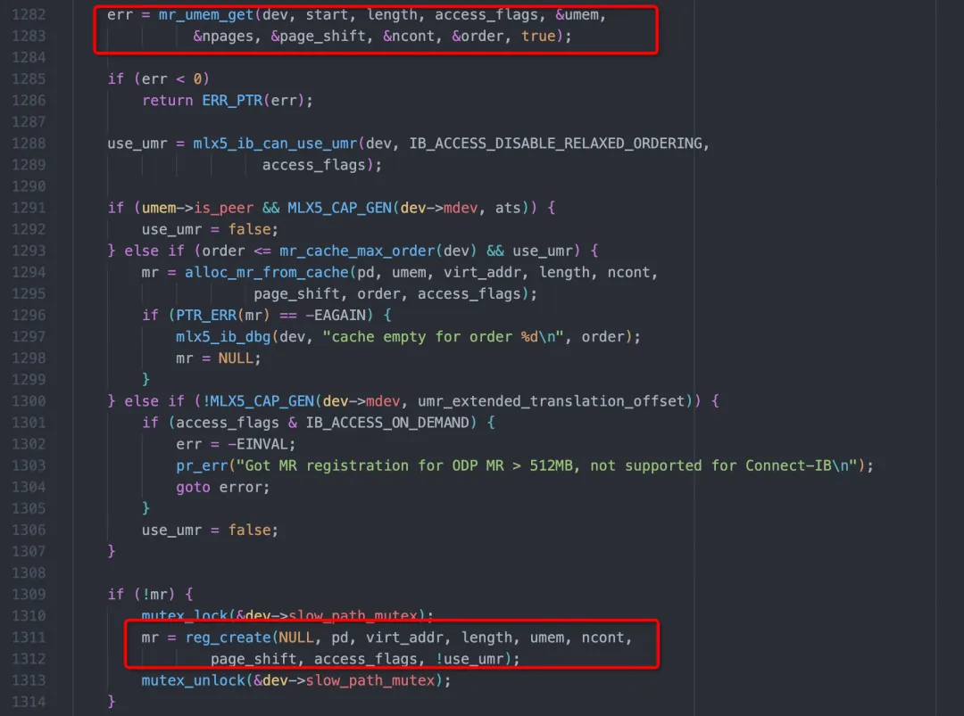
This function mainly achieves two things. One is to pin the user-mode memory through the mr_umem_get and obtain the physical address. The other is to send the command of creating mkey to the NIC through reg_create. mr_umem_get will eventually call the function __ib_umem_get in the ib_core.ko:
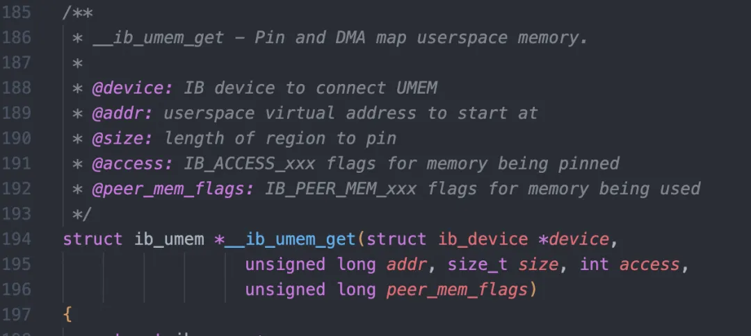
This function will prevent unexpected changes (such as swap) in the mapping of the user memory through the pin_user_pages_fast interface of the kernel.
reg_create sends the command of creating mkey based on the command format defined in the reference manual:
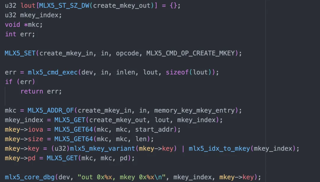
After the above process, a mkey object will be created in the NIC:
mkey 0xdd5d
virt_addr 0xdb1000, length 0x2000, access_flags 0x100007
pas[0] 0x3e07a92003
pas[1] 0x3e106a6003
When the NIC receives the virtual address, it can know what the actual physical page is and control permissions.
Now we can answer the above questions:
1. Security risk: Can the user-mode app read and write any physical memory by using NIC?
No, RDMA implements strict memory protection through PD and MR.
2. Address mapping: The user-mode app uses the virtual address, and the actual physical address is managed by the operating system. How can the NIC know the mapping between the virtual address and the physical address?
The drivers will tell the NIC the mapping relationship. In the subsequent data flow, the NIC will convert it.
3. Changes of address mapping: The operating system may swap and compress memory, and it also has some complex mechanisms, such as Copy-On-Write. In these cases, how can we ensure the accuracy of the address accessed by the NIC?
It can be guaranteed by calling pin_user_pages_fast through the drivers. In addition, the user-mode driver will mark the registered memory with the DONT_FORK flag to avoid Copy-On-Write.
The basic unit of interaction between the software and hardware of RDMA is the Work Queue. Work Queue is a circular queue with a single producer and a single consumer. Based on different functions, the Work Queue is divided into SQ (send queue), RQ (receive queue), CQ (completion queue), and EQ (event queue).
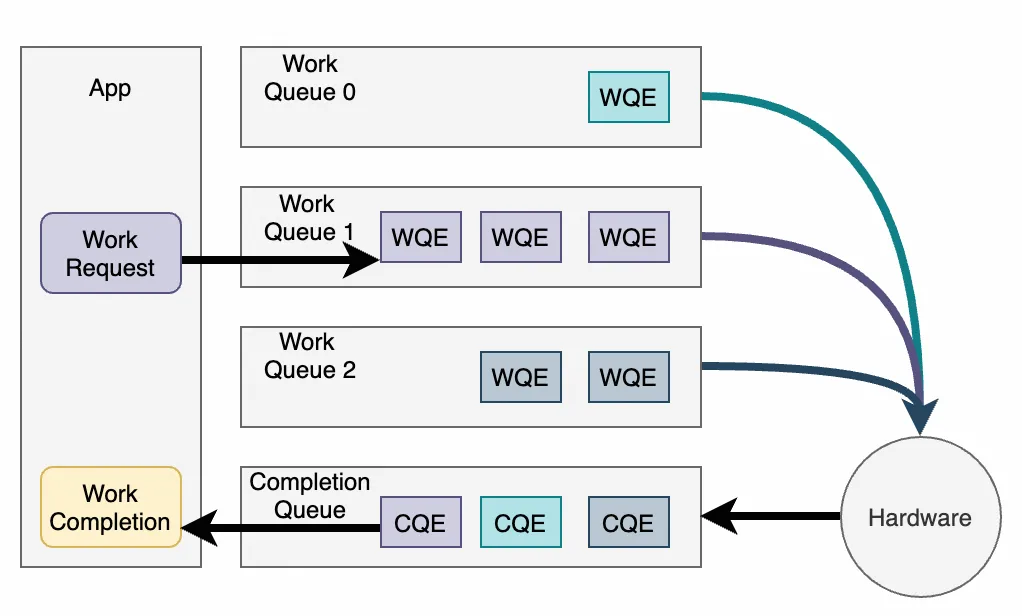
The process of sending an RDMA request is as follows:
We will analyze it with a practical example for an in-depth understanding of the whole process:
uint32_t send_demo(struct ibv_qp *qp, struct ibv_mr *mr)
{
    struct ibv_send_wr sq_wr = {}, *bad_wr_send = NULL;
    struct ibv_sge sq_wr_sge[1];

    // Send the MR data.
    sq_wr_sge[0].lkey = mr->lkey;
    sq_wr_sge[0].addr = (uint64_t)mr->addr;
    sq_wr_sge[0].length = mr->length;

    sq_wr.next = NULL;
    sq_wr.wr_id = 0x31415926; // Requested ID that can be matched when WC is received.
    sq_wr.send_flags = IBV_SEND_SIGNALED; // Tell the NIC that this request is to generate CQE.
    sq_wr.opcode = IBV_WR_SEND;
    sq_wr.sg_list = sq_wr_sge;
    sq_wr.num_sge = 1;

    ibv_post_send(qp, &sq_wr, &bad_wr_send); // Submit the request to the NIC.

    struct ibv_wc wc = {};
    while (ibv_poll_cq(qp->send_cq, 1, &wc) == 0) {
        continue;
    }

    if (wc.status != IBV_WC_SUCCESS || wc.wr_id != 0x31415926) {
        exit(__LINE__);
    }

    return 0;
}
The core of this code is ibv_post_send and ibv_poll_cq. The former is used to submit the request to the NIC, while the latter is used to poll CQ to check if any requests are completed.
In addition, the IB specification defines several abstractions:
Open debug of rdma-core and we can see two logs:
dump wqe at 0x7fc59b357000
0000000a 00115003 00000008 00000000
00000000 c0000000 00000000 00000000
0000022a 00008a0b 00007fc5 9a5b2000

mlx5_get_next_cqe:565: dump cqe for cqn 0x4c2:
00000000 00000000 00000000 00000000
00000000 00000000 00000000 00000000
00000000 00000000 00000000 00000000
00004863 2a39b102 0a001150 00003f00
The first log is WQE the rdma-core event submits to the NIC after we call ibv_post_send.
The second log is CQE which we receive from the NIC after we call ibv_poll_cq.
On the NVIDIA NIC, ibv_post_send finally calls _mlx5_post_send:
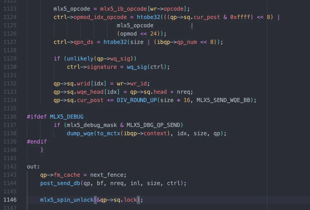
The core functionalities of this function are:
According to the NVIDIA manual, WQE for a Send request consists of two parts:
Control segment:
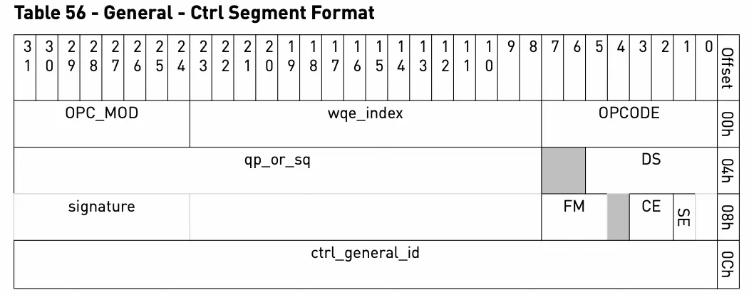
Data segment:
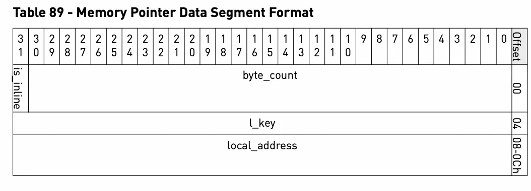
According to the definition in the manual, we will parse WQE in the above log:
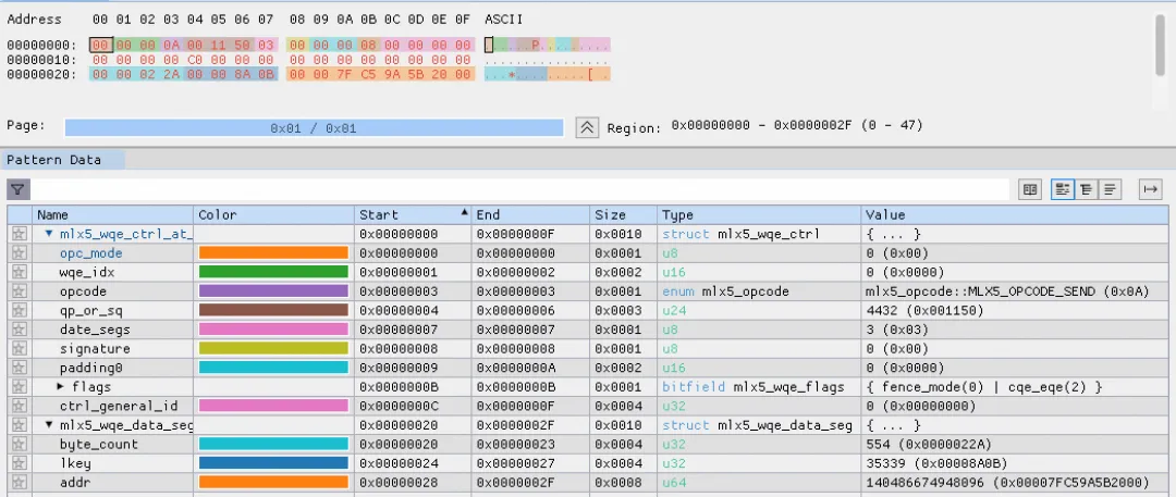
It can be seen that it is similar to ibv_send_wr filled in by the software. Note that wr_id we filled in does not appear in WQE. In fact, this wr_id is stored in rdma-core. As WQE is processed in order, when receiving CQE, we can find ibv_send_wr that was originally submitted.
The function post_send_db is simple, but with many details:
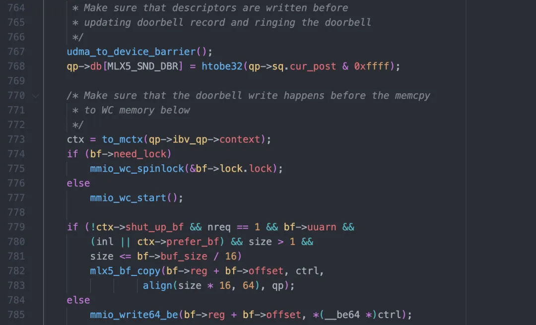
First, this function adds a memory barrier to ensure that when Doorbell arrives in the hardware, the WQE built earlier is visible.
Then, update Doorbell information of QP (actually the tail of the queue).
Finally, write it to the register of the NIC through mmio_write64_be and tell the NIC to send it.
mmio_write64_be uses the sse instruction (on x86) and the first part of WQE (the control segment above) is written to the register of the NIC:

It is actually an assignment operation which is equivalent to the following statement:
*(uint64_t)(bf->reg + bf->offset) = *(uint64_t *)ctrl;SSE is mainly used to ensure atomicity and avoid the NIC receiving the first 4 bytes and then the last 4 bytes.
It seems that all the emphasis is on bf->reg. What is this buffer? Why can the NIC receive the event after the software writes a uint64 to this buffer?
It can be seen in gdb that this bf->reg looks like an ordinary virtual address, but gdb fails to read it.

Take a look at the maps information for the process:

The memory is mapped to Write Only, so the reading fails. Then what is the memory?
Look at the page table with crash:
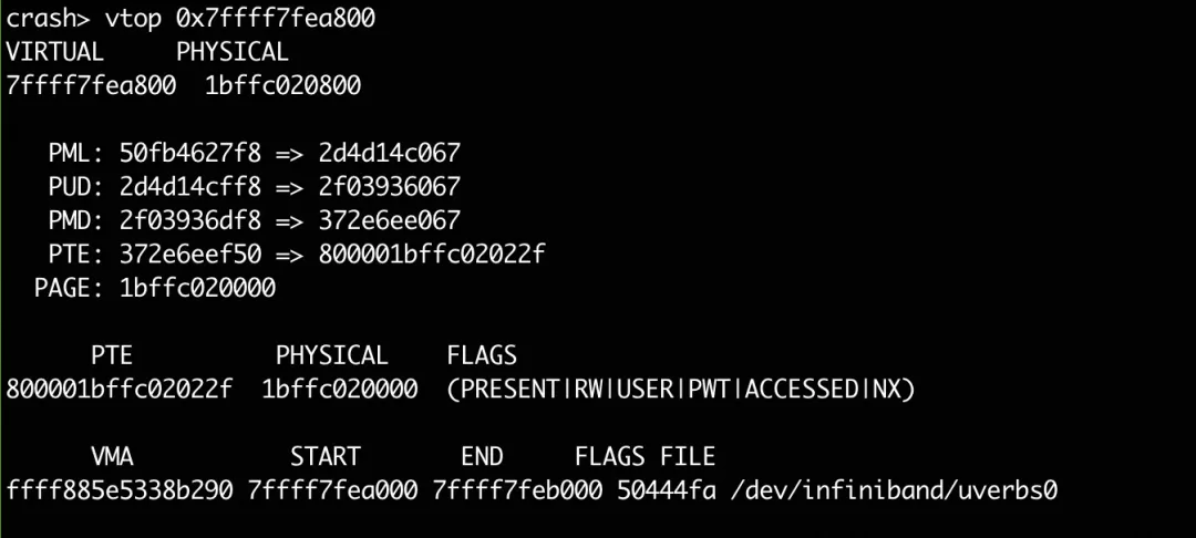
The physical address is 1bffc020800. Through the /proc/iomem, we can see that this physical address belongs to the PCI device 0000:3b:00.0:
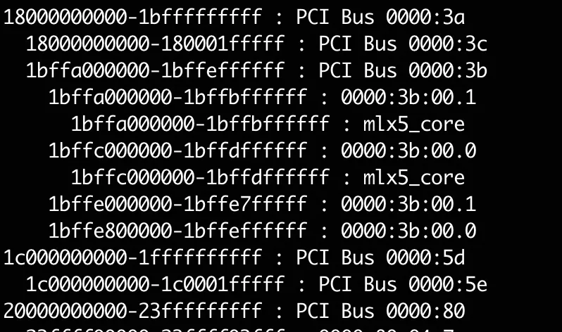
This device is exactly the RDMA NIC we used, and this address is located at BAR0:
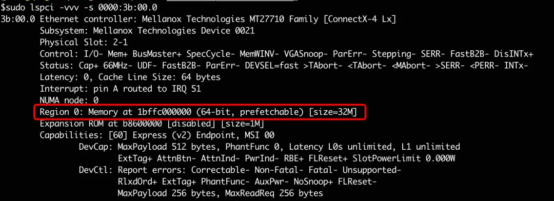
According to the NVIDIA manual, this address area written by the software is called UAR (User Access Region). UAR is a part of the PCI address space. It is mapped directly into the memory of the application by the NIC driver. When the software writes Doorbell to UAR, the NIC will receive a message from PCI, thus knowing that the software needs to send data.
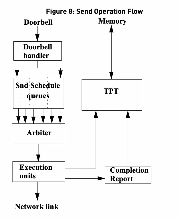
Thereafter, the NIC is scheduled and arbitrated to pull WQE for execution. In the process of execution, the NIC will first extract mkey and address from WQE, then send them to the TPT (Translation and Protection) unit to query information about mkey. The NIC will obtain the address and permission from the unit, perform DMA after verification, and finally send the data to the physical interface. When the data is sent and confirmed by the opposite terminal, the NIC generates CQE to notify the software. The software can recycle resources only after receiving CQE. This is different from the Socket interface which allows copying. After the software finishes calling write, resources can be recycled. However, RDMA is zero-copy, which makes the management of the resource lifecycle more complicated.
So far, the basic working principle of RDMA and the interaction mechanism between software and hardware have been introduced. The principle of RDMA technology is very simple. That is, whether it can bypass all restrictions and directly send data to users. However, RDMA is facing challenges such as complex programming and debugging, heavy dependence on hardware, and unavailability of long-distance transmission. For I/O-intensive services, RDMA can save CPU and achieve high throughput and low latency. But for computing-intensive services or hardware-independent services, TCP is more appropriate.
Disclaimer: The views expressed herein are for reference only and don't necessarily represent the official views of Alibaba Cloud.

1,320 posts | 464 followers
FollowApsaraDB - May 29, 2025
Alibaba Cloud Community - November 14, 2025
Alibaba Cloud Community - July 27, 2022
ApsaraDB - April 9, 2025
Alibaba Clouder - September 19, 2018
Alibaba Clouder - February 4, 2019

1,320 posts | 464 followers
Follow Accelerated Global Networking Solution for Distance Learning
Alibaba Cloud offers an accelerated global networking solution that makes distance learning just the same as in-class teaching.
Learn More Networking Overview
Connect your business globally with our stable network anytime anywhere.
Learn More Remote Rendering Solution
Connect your on-premises render farm to the cloud with Alibaba Cloud Elastic High Performance Computing (E-HPC) power and continue business success in a post-pandemic world
Learn More Database Gateway
A tool product specially designed for remote access to private network databases
Learn MoreMore Posts by Alibaba Cloud Community
5955237907257947 January 26, 2025 at 4:10 pm
The link to "(https://github.com/linux-rdma/rdma-core)." needs to be fixed. The URL is correct but when clicking on it, it goes to the following which seems wrong: https://github.com/linux-rdma/rdma-core).?spm=a2c65.11461447.0.0.64044003A1Bwyd