By Yue Meng and compiled by Maohe
This article was prepared based on the live courses on Apache Flink given by Yue Meng, an Apache Flink contributor and R&D engineer for the real-time computing platform of NetEase Cloud Music. It describes two aspects of the Flink job execution process: (1) how to go from a program to a physical execution plan and (2) how to schedule and execute the physical execution plan.
Flink implements transformations at four levels: transformation from a program to a StreamGraph, transformation from the StreamGraph to a JobGraph, transformation from the JobGraph to an ExecutionGraph, and transformation from the ExecutionGraph to a physical execution plan. After a program is executed, a directed acyclic graph (DAG) or logical execution graph is generated, as shown in the following figure.
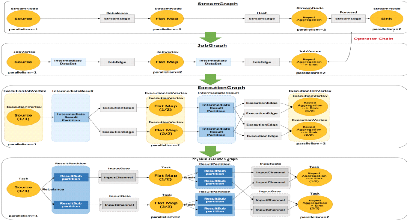
This article first introduces the four levels of transformations and uses case studies to provide a more detailed explanation.
The process of transforming a program to a StreamGraph is as follows:
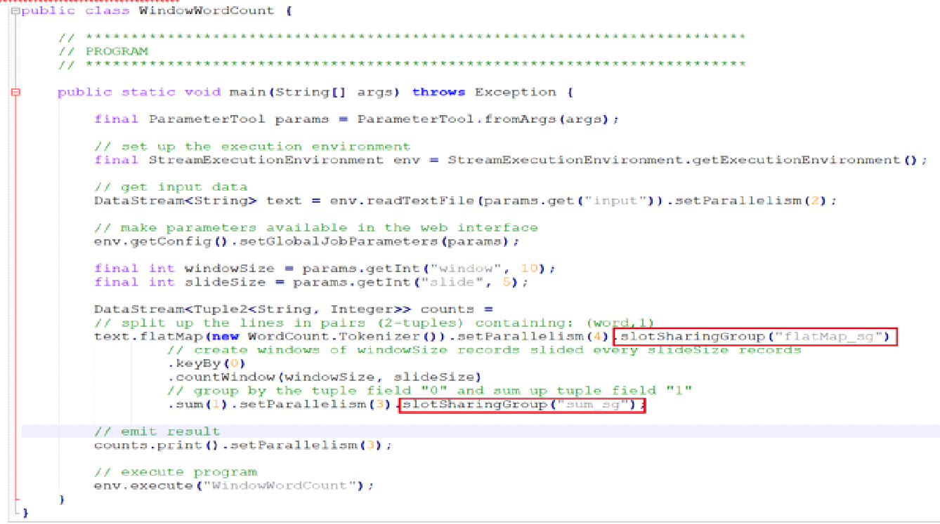
Use WindowWordCount to view the transformation from code to the StreamGraph. In the flatMap transform, the slot sharing group is set to flatMap_sg, and parallelism is set to 4. In the aggregate operation, the slot sharing group is set to sum_sg and parallelism is set to 3 for sum() and counts(). These settings are intended to help demonstrate the subsequent nesting process, which is related to the parallelism of upstream and downstream nodes and the upstream sharing groups.
Based on the code of WindowWordCount, readTextFile() creates a transform with the ID 1. flatMap() creates a transform with the ID 2. keyBy() creates a transform with the ID 3. sum() creates a transform with the ID 4. counts() creates a transform with the ID 5.
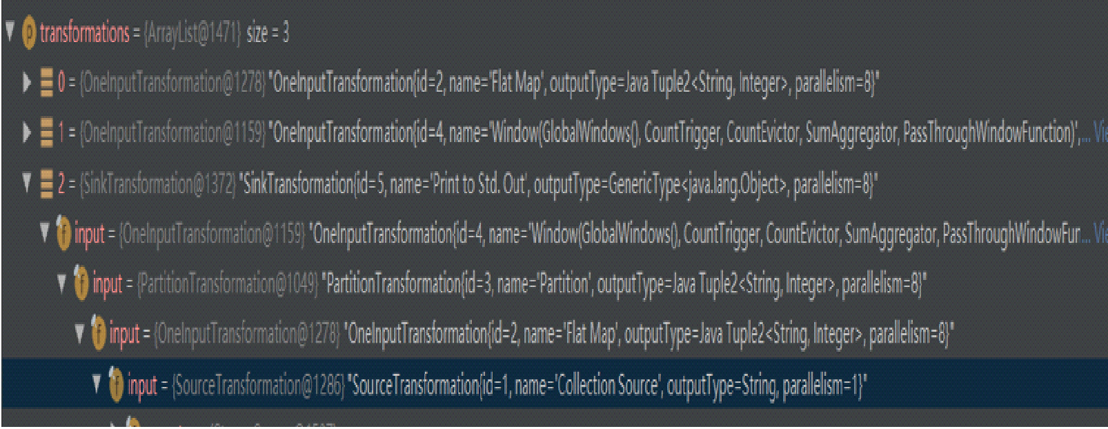
The following figure shows the transform structure. The first transform belongs to flatMap. The second transform belongs to Window. The third transform belongs to SinkTransform. The transform structure also shows the input of each transform.
The concepts of StreamNode and StreamEdge are explained as follows.
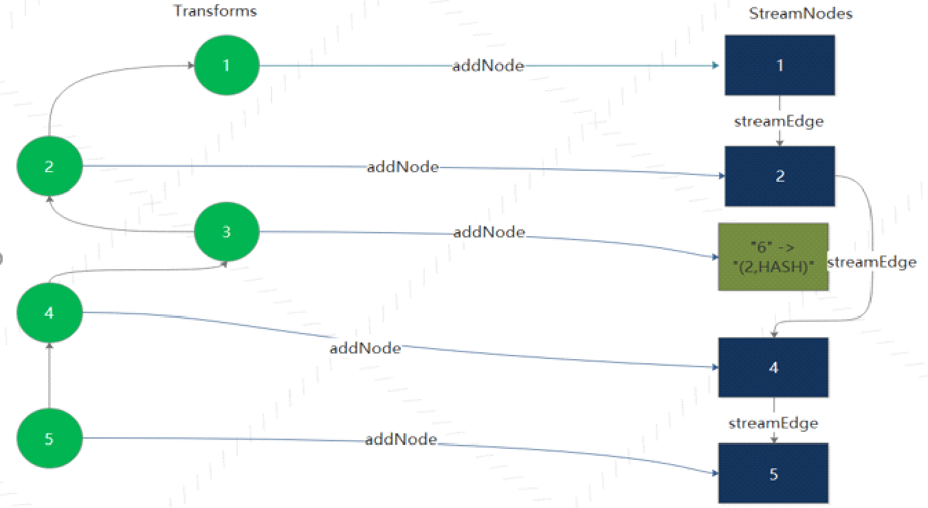
The following figure shows how the WindowWordCount transforms into a StreamGraph. The transformations of StreamExecutionEnvironment include three transforms: Flat Map (ID: 2), Window (ID: 4), and Sink (ID: 5).
During a transform operation, the input is recursively processed to create a StreamNode. Then upstream and downstream StreamNodes are connected by a StreamEdge. Some transform operations, such as PartitionTransformtion, create virtual nodes rather than StreamNodes.
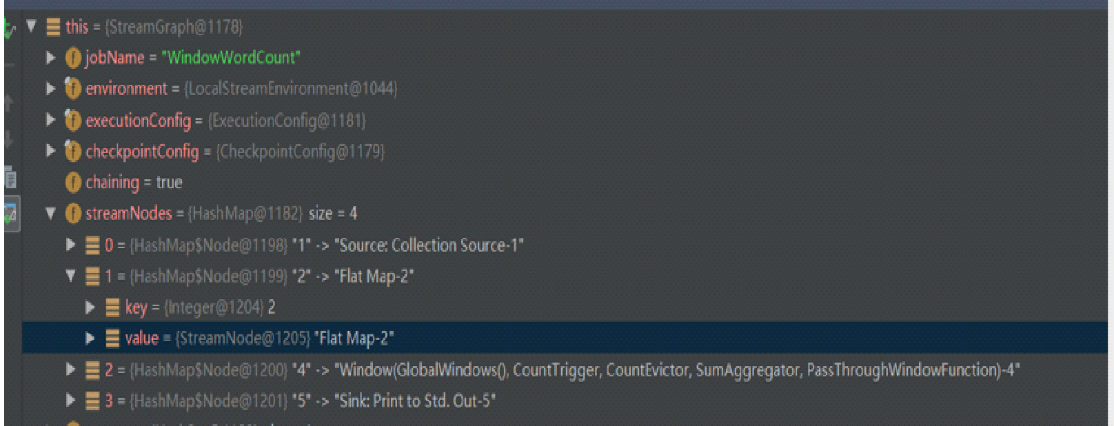
After the transformation, a StreamNode has four transforms: Source, Flat Map, Window, and Sink.
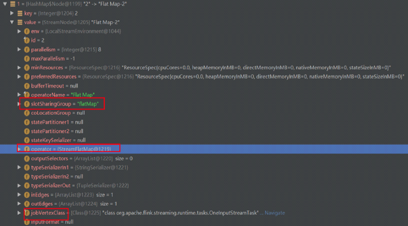
Each StreamNode object contains runtime information, including the parallelism, slotSharingGroup, and execution class.
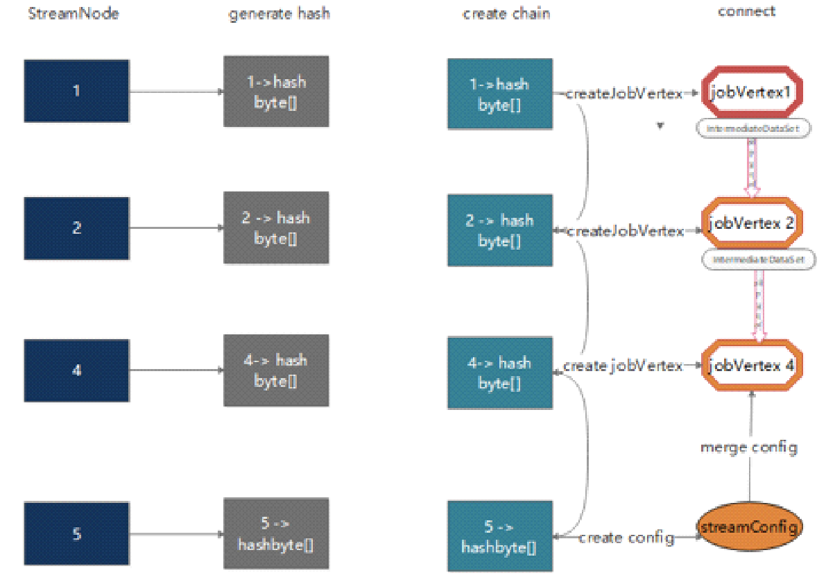
The process of transforming a StreamGraph to a JobGraph is as follows:
The following conditions must be met for operators to be nested:

The preceding figure shows the JobGraph object structure. taskVertices only includes three TaskVertexes: Window, Flat Map, and Source. The Sink operator is nested in the Window operator.
When a Flink task fails, it's possible to recover each operator from the checkpoint to the pre-failure status based on the JobVertexID, namely, the hash value. The hash value of each operator must remain unchanged when the same task is recovered, so as to obtain the corresponding status.
If we specify a hash value for a node, a byte array with a length of 16 is generated based on the hash value. If no hash value is specified for a node, a hash value is generated based on the location of the node.
Three things must be considered in this process:
1) The number of nodes that are processed before the current StreamNode is specified as the ID of this StreamNode and added to the hasher.
2) The system traverses all StreamEdges that are output by the current StreamNode and determines whether this StreamNode can be connected to the target StreamNode of each StreamEdge. If it's possible, then the ID of the target StreamNode is added to the hasher and set to the same value as the ID of the current StreamNode.
3) Bitwise operations are performed on the byte data that is generated in the preceding two steps and the byte data of all the input StreamNodes of the current StreamNode. The resulting byte data is used as the byte array of the current StreamNode, with a length of 16.
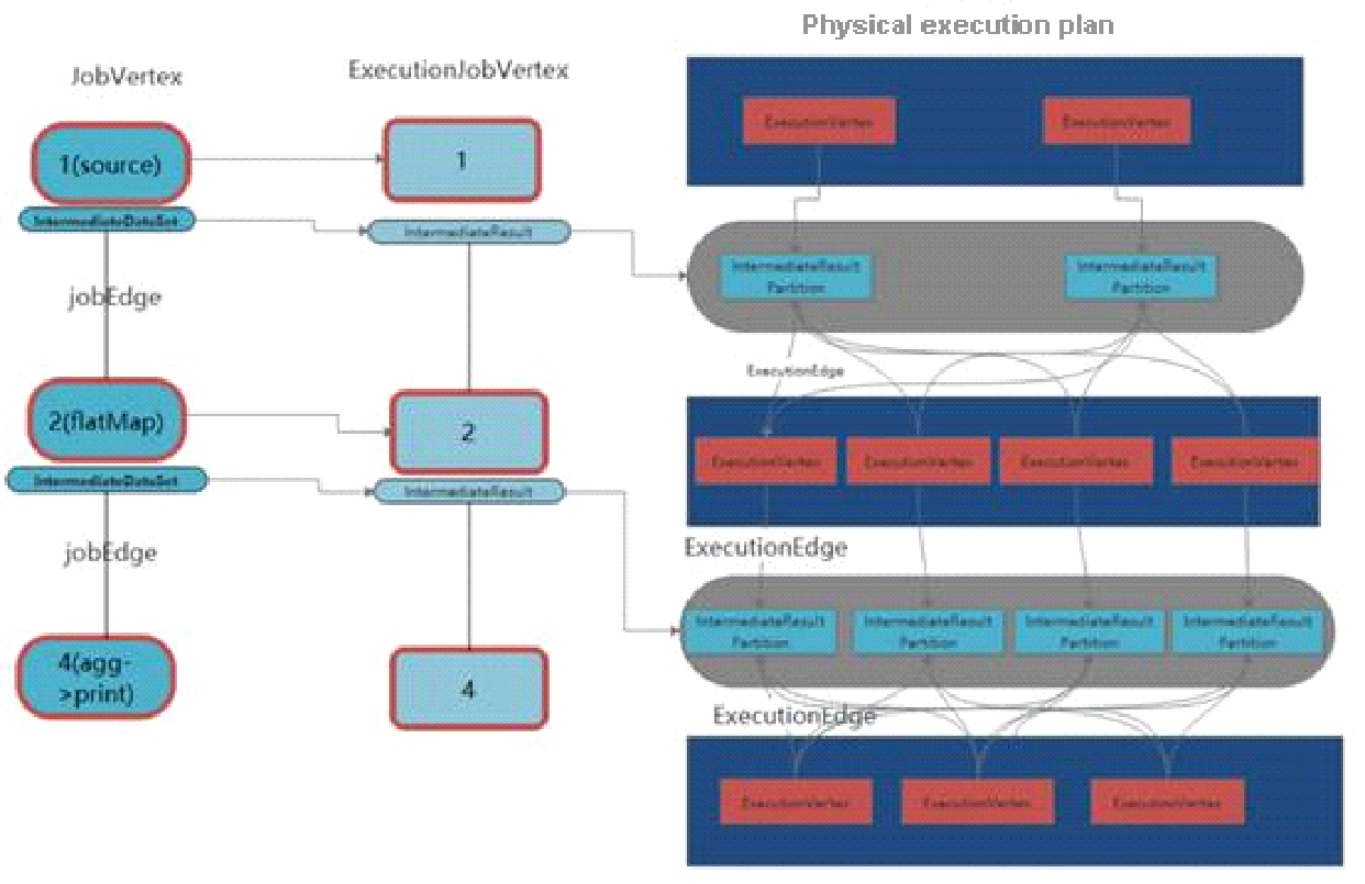
The process of transforming a JobGraph to an ExecutionGraph and then to a physical execution plan is as follows:
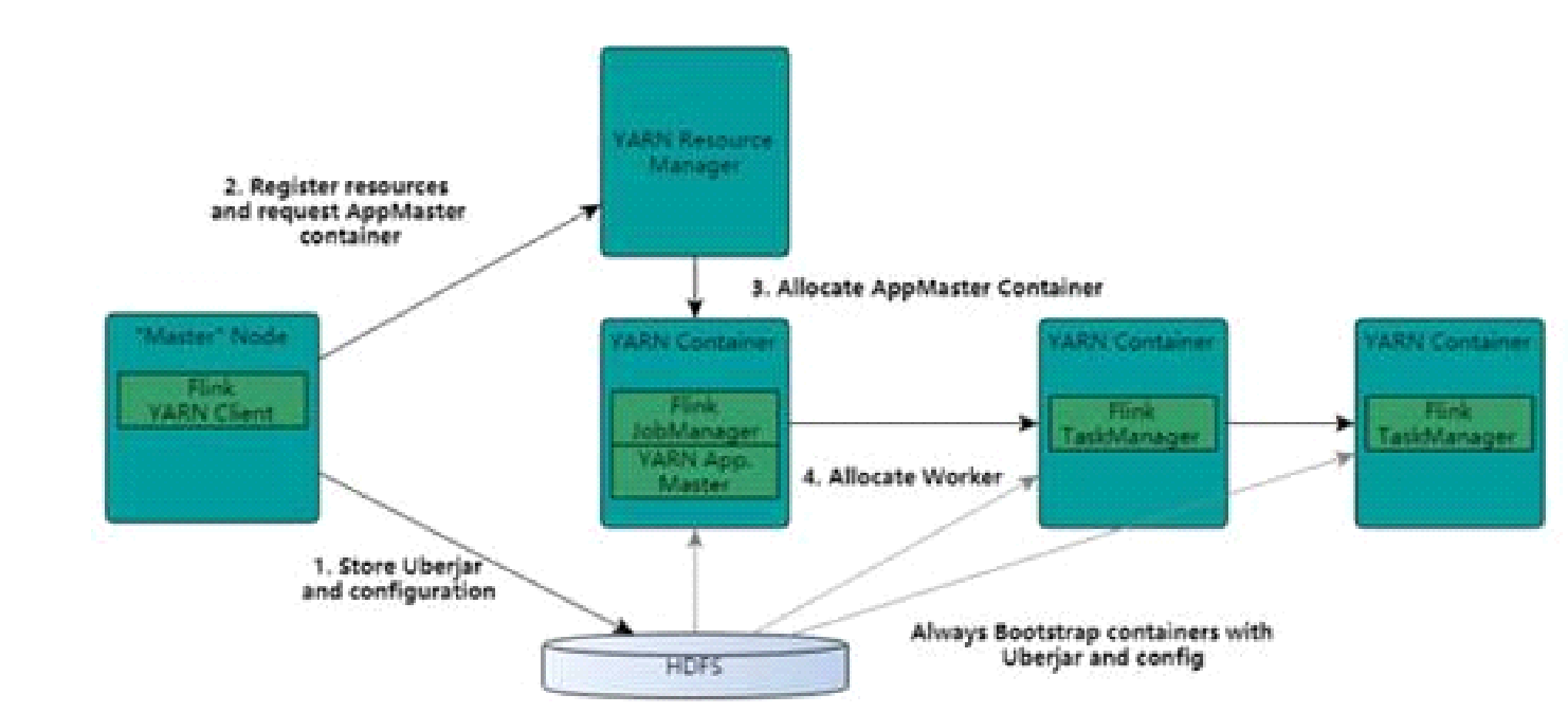
The YARN-based architecture is similar to the Spark on YARN mode. Clients submit applications to the Resource Manager (RM) to run the applications. The RM allocates the first container to run the Application Master (AM), which monitors and manages resources. The Flink on YARN mode is similar to the cluster mode of Spark on YARN, in which a driver runs like a thread of the AM. In Flink on YARN mode, the JobManager is started inside a container to schedule and allocate tasks in a way similar to the scheduling of drivers. The YARN AM and Flink JobManager are inside the same container, which allows the YARN AM to know the Flink JobManager's address and apply for a container to start the Flink TaskManager. After Flink successfully runs in the YARN cluster, the Flink YARN client submits a Flink job to the Flink JobManager and implements mapping, scheduling, and computing.
Flink 1.5 introduces a new concept called Dispatcher. The Dispatcher receives job submission requests from clients and starts jobs on a cluster manager on behalf of the clients.
The dispatcher serves the following two purposes:
1) It provides some cluster managers with a centralized instance to create and monitor jobs.
2) It assumes the JobManager role in Standalone mode and waits for job submissions. The Dispatcher is optional in YARN and incompatible with Kubernetes.
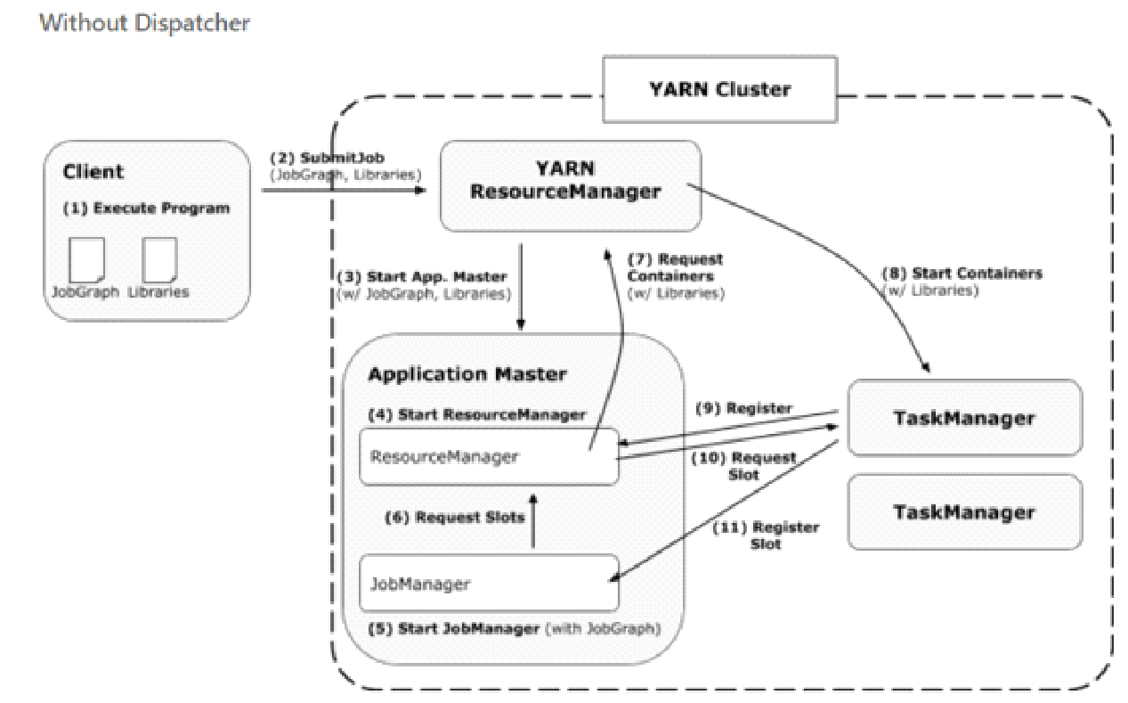
After a client submits a JobGraph and a dependency JAR package to the YARN RM, the YARN RM allocates the first container to start the AM. The AM starts a Flink RM and JobManager. The JobManager applies for slots from the Flink RM based on the ExecutionGraph and physical execution plan that is created based on the JobGraph. The Flink RM manages these slots and requests. If no slots are available, the JobManager applies for a container from the YARN RM. The container is started and registered to the Flink RM. Finally, the JobManager deploys the subtask to a slot of the container.
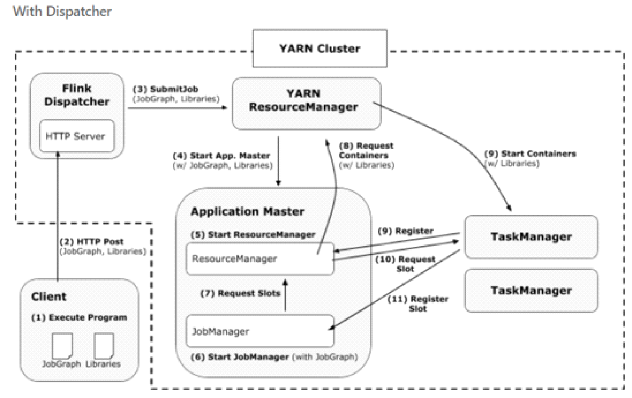
The Dispatcher allows the client to submit jobs to the YARN RM directly through an HTTP server.
The new framework provides four benefits:
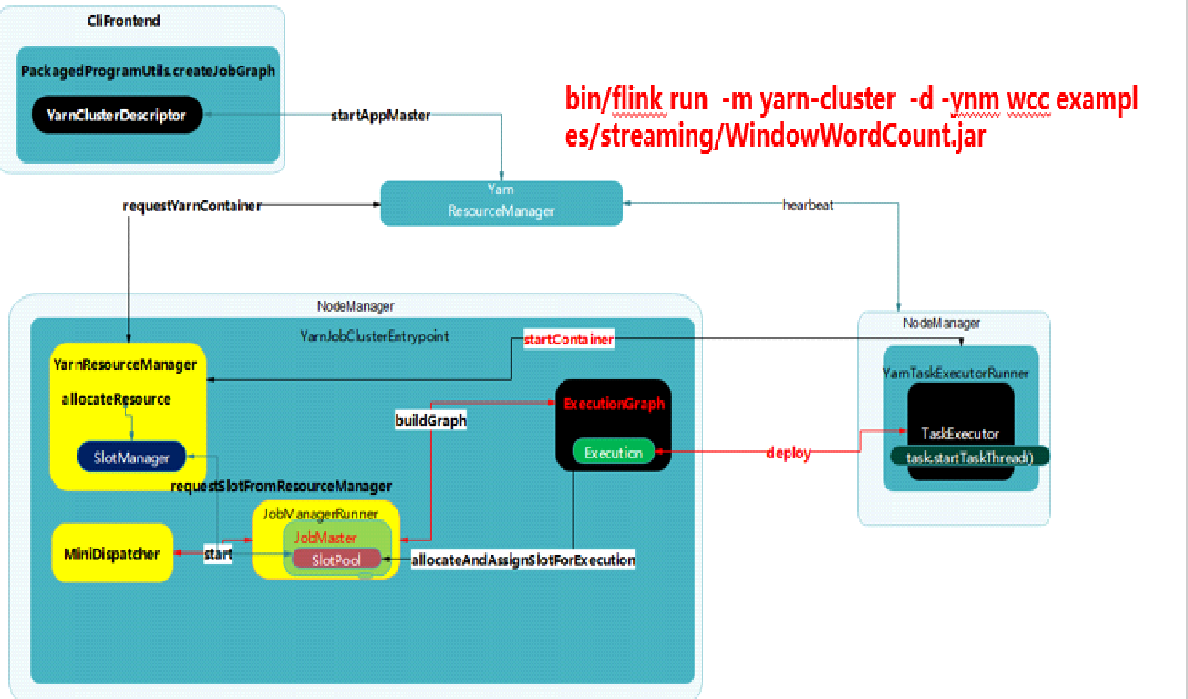
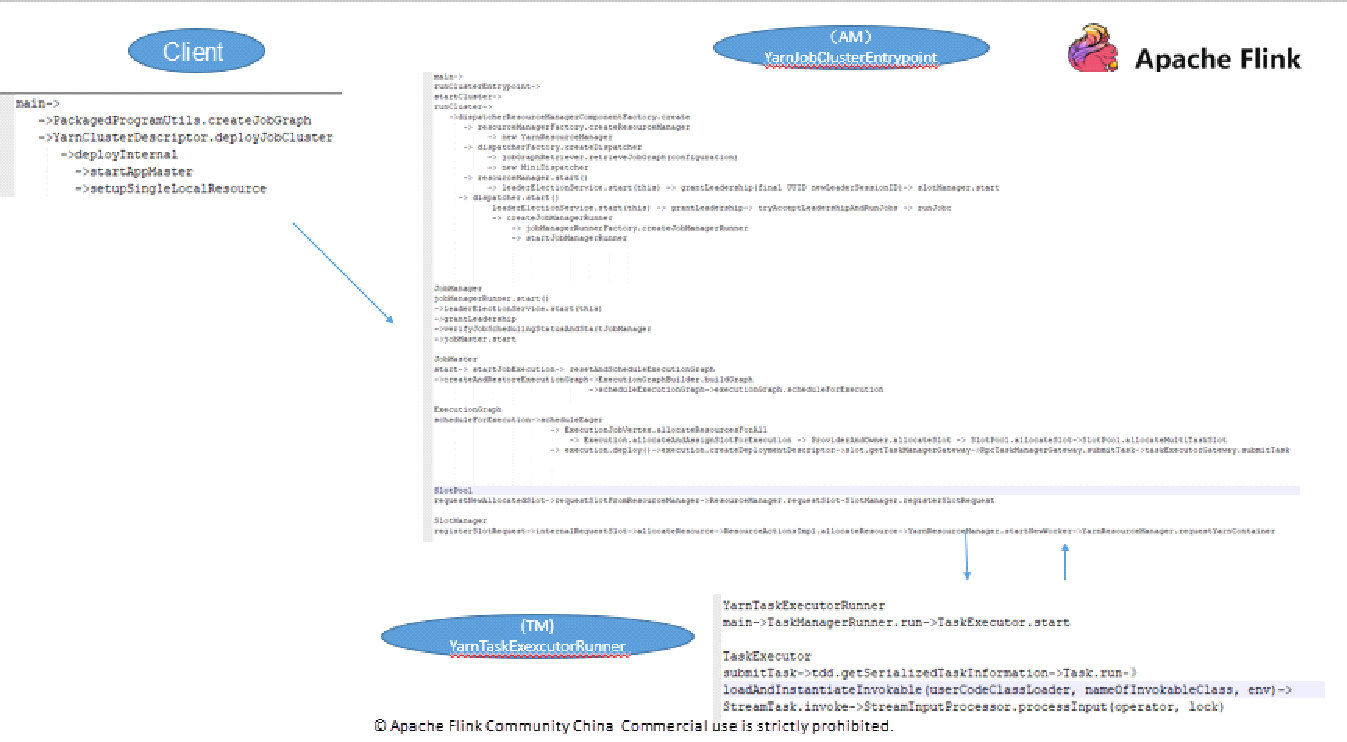
The Single Cluster Job on YARN mode involves three instance objects:
1) clifrontend
2) YarnJobClusterEntrypoint (Master)
3) YarnTaskExecutorRunner (slave)
The following figure shows the task execution code.
The system calls the StreamTask's invoke method. The execution process is as follows:
The following code shows how the task is processed by the run method of OneInputStreamTask that corresponds to flatMap:
@Override
    protected void run() throws Exception {
        // cache processor reference on the stack, to make the code more JIT friendly
        final StreamInputProcessor<IN> inputProcessor = this.inputProcessor;

        while (running && inputProcessor.processInput()) {
            // all the work happens in the "processInput" method
        }
    }
Data is processed by calling processInput() of the StreamInputProcessor. The following code includes the user's processing logic:
public boolean processInput() throws Exception {
        if (isFinished) {
            return false;
        }
        if (numRecordsIn == null) {
            try {
                numRecordsIn = ((OperatorMetricGroup) streamOperator.getMetricGroup()).getIOMetricGroup().getNumRecordsInCounter();
            } catch (Exception e) {
                LOG.warn("An exception occurred during the metrics setup.", e);
                numRecordsIn = new SimpleCounter();
            }
        }

        while (true) {
            if (currentRecordDeserializer != null) {
                DeserializationResult result = currentRecordDeserializer.getNextRecord(deserializationDelegate);

                if (result.isBufferConsumed()) {
                    currentRecordDeserializer.getCurrentBuffer().recycleBuffer();
                    currentRecordDeserializer = null;
                }

                if (result.isFullRecord()) {
                    StreamElement recordOrMark = deserializationDelegate.getInstance();
                    //处理watermark
                    if (recordOrMark.isWatermark()) {
                        // handle watermark
                        //watermark处理逻辑,这里可能引起timer的trigger
                        statusWatermarkValve.inputWatermark(recordOrMark.asWatermark(), currentChannel);
                        continue;
                    } else if (recordOrMark.isStreamStatus()) {
                        // handle stream status
                        statusWatermarkValve.inputStreamStatus(recordOrMark.asStreamStatus(), currentChannel);
                        continue;
                        //处理latency watermark
                    } else if (recordOrMark.isLatencyMarker()) {
                        // handle latency marker
                        synchronized (lock) {
                            streamOperator.processLatencyMarker(recordOrMark.asLatencyMarker());
                        }
                        continue;
                    } else {
                        //用户的真正的代码逻辑
                        // now we can do the actual processing
                        StreamRecord<IN> record = recordOrMark.asRecord();
                        synchronized (lock) {
                            numRecordsIn.inc();
                            streamOperator.setKeyContextElement1(record);
                            //处理数据
                            streamOperator.processElement(record);
                        }
                        return true;
                    }
                }
            }

            //这里会进行checkpoint barrier的判断和对齐,以及不同partition 里面checkpoint barrier不一致时候的,数据buffer,

            final BufferOrEvent bufferOrEvent = barrierHandler.getNextNonBlocked();
            if (bufferOrEvent != null) {
                if (bufferOrEvent.isBuffer()) {
                    currentChannel = bufferOrEvent.getChannelIndex();
                    currentRecordDeserializer = recordDeserializers[currentChannel];
                    currentRecordDeserializer.setNextBuffer(bufferOrEvent.getBuffer());
                }
                else {
                    // Event received
                    final AbstractEvent event = bufferOrEvent.getEvent();
                    if (event.getClass() != EndOfPartitionEvent.class) {
                        throw new IOException("Unexpected event: " + event);
                    }
                }
            }
            else {
                isFinished = true;
                if (!barrierHandler.isEmpty()) {
                    throw new IllegalStateException("Trailing data in checkpoint barrier handler.");
                }
                return false;
            }
        }
    }
streamOperator.processElement(record) calls the user's code processing logic. Here, we assume that the operator is StreamFlatMap.
 @Override
    public void processElement(StreamRecord<IN> element) throws Exception {
        collector.setTimestamp(element);
        userFunction.flatMap(element.getValue(), collector);//用户代码
    }
If you have any questions, please do comment or reach out to your local sales team.
Analysis of Network Flow Control and Back Pressure: Flink Advanced Tutorials

159 posts | 46 followers
FollowApache Flink Community China - September 16, 2020
Apache Flink Community China - September 16, 2020
Apache Flink Community China - September 16, 2020
Apache Flink Community China - September 16, 2020
Apache Flink Community China - December 25, 2020
Apache Flink Community China - December 25, 2019

159 posts | 46 followers
Follow Realtime Compute for Apache Flink
Realtime Compute for Apache Flink offers a highly integrated platform for real-time data processing, which optimizes the computing of Apache Flink.
Learn More Message Queue for Apache Kafka
A fully-managed Apache Kafka service to help you quickly build data pipelines for your big data analytics.
Learn More Resource Management
Organize and manage your resources in a hierarchical manner by using resource directories, folders, accounts, and resource groups.
Learn More Super App Solution for Telcos
Alibaba Cloud (in partnership with Whale Cloud) helps telcos build an all-in-one telecommunication and digital lifestyle platform based on DingTalk.
Learn MoreMore Posts by Apache Flink Community
Start building with 50+ products and up to 12 months usage for Elastic Compute Service
Get Started for Free Get Started for Free