By Zhang Jun and compiled by Zhang Youliang, an Apache Flink community volunteer
This article is based on the live courses on Apache Flink given by Zhang Jun, an Apache Flink contributor and R&D Director of OPPO's big data platform. This article consists of the following parts:
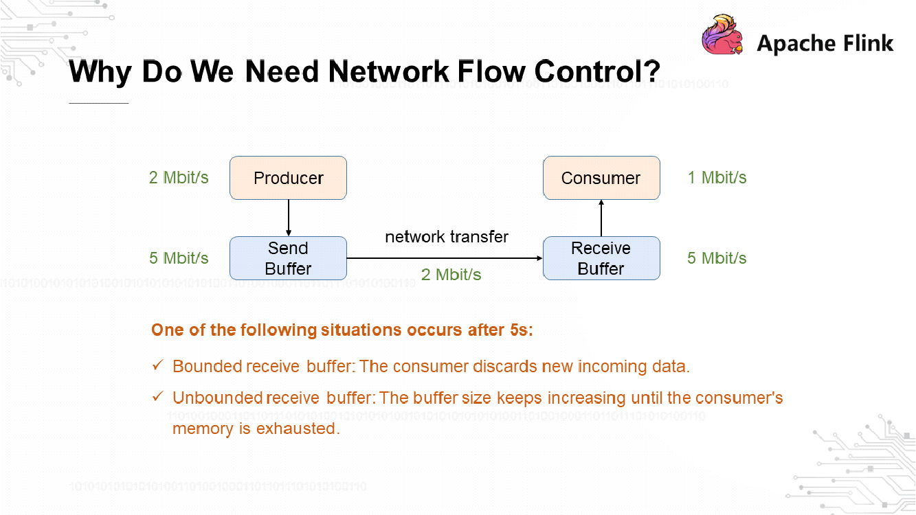
The preceding figure shows a simplified schematic diagram of network flow control. The producer has 2 Mbit/s throughput and the consumer has 1 Mbit/s throughput. During network communication, the producer is 1 Mbit/s faster than the consumer. Assume that the producer has a send buffer and that the consumer has a receive buffer, with a throughput of 2 Mbit/s at the network end. The receive buffer may crash after 5s, resulting in one of the following situations:
1) If the receive buffer is bounded, it discards new incoming data.
2) If the receive buffer is unbounded, its size keeps increasing until it exhausts the consumer's memory resources.
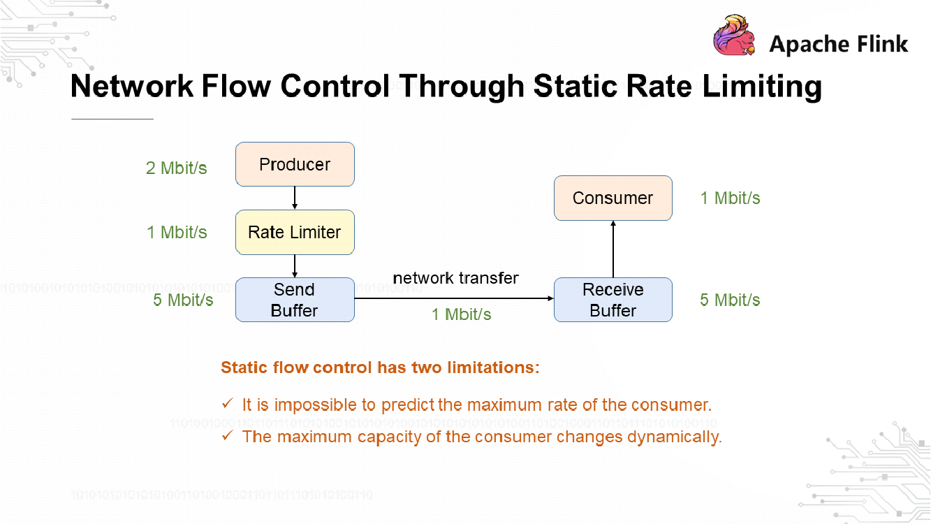
The difference between the upstream and downstream rates is eliminated through network flow control. A typical solution is to implement a static rate limiter at the producer end to reduce the producer's transmit rate from 2 Mbit/s to 1 Mbit/s when data is sent from the send buffer. This makes the producer's transmit rate the same as the consumer's processing rate and therefore prevents the receive buffer from using up the consumer's memory resources. However, this solution has two limitations:
1) It is impossible to predict the maximum rate of the consumer.
2) The maximum capacity of the consumer changes dynamically.
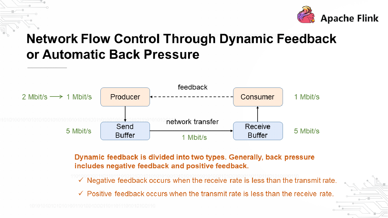
If network flow control is implemented through dynamic feedback, also known as automatic back pressure, the consumer is required to promptly send feedback to inform the producer of the maximum transmission rate that the consumer might support. Dynamic feedback is divided into two types:
1) Negative Feedback: When the receiving rate is less than the transmit rate, the consumer sends negative feedback to ask the producer to reduce the transmit rate.
2) Positive Feedback: When the transmit rate is less than the receiving rate, the consumer sends positive feedback to ask the producer to increase the transmit rate.
Let's look at two typical cases.
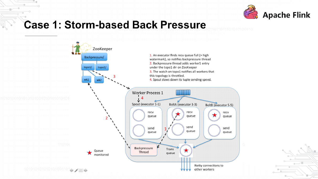
The preceding figure shows how Storm implements back pressure. Each bolt has a thread that monitors back pressure, which is called a backpressure thread. When serious congestion of the receiving queue within the bolt is detected, the thread writes the congestion situation to ZooKeeper. The spout keeps listening to ZooKeeper, and data transmission stops when the spout detects back pressure. This ensures upstream and downstream rates match each other.
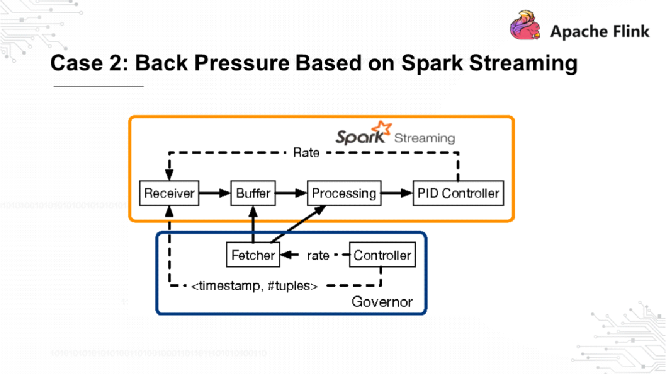
Spark Streaming implements feedback in a way similar to Storm. As shown in the preceding figure, the fetcher collects metrics from the buffer and processing nodes in real time. Then, the controller sends rate feedback to the receiver so that the upstream and downstream rates match each other.
Before we get to this question, we need to understand Flink's network transmission architecture.
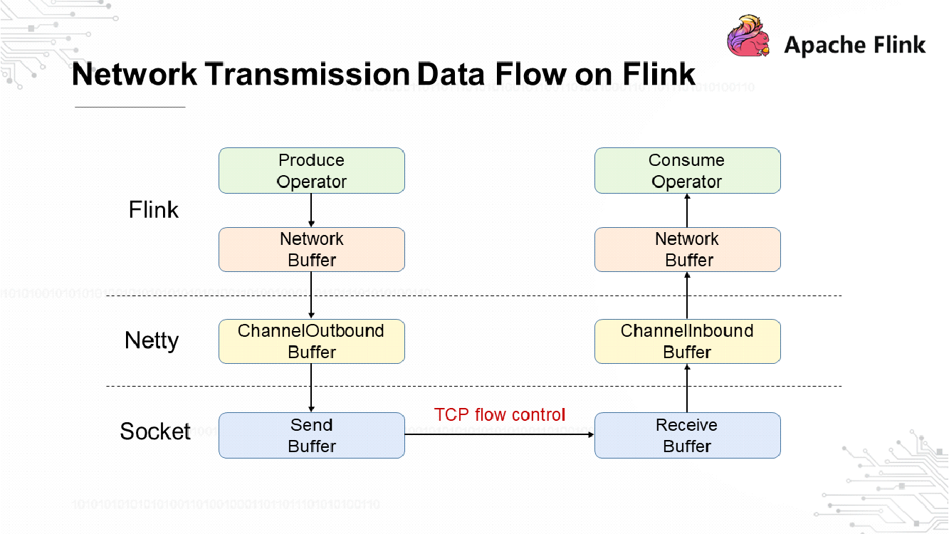
The preceding figure shows the basic data flow of network transmission in Flink. The transmitting end implements an internal process before sending network data. The network buffer at the transmit end uses underlying Netty for communication, and Netty has a ChannelOutboundBuffer. The socket has a send buffer for sending network requests. The receiving end has three buffers that correspond to the buffers at the transmitting end. If you are familiar with computer networks, you should know that TCP implements flow control by default. Flink versions earlier than V1.5 implement feedback through TCP-based flow control.
The following figure shows the format and structure of a TCP packet. Each TCP packet has a sequence number and an ACK number to ensure reliable TCP data transmission. A packet also includes the window size that allows the receiving end, when returning a response, to inform the transmit end of how much data can still be sent.
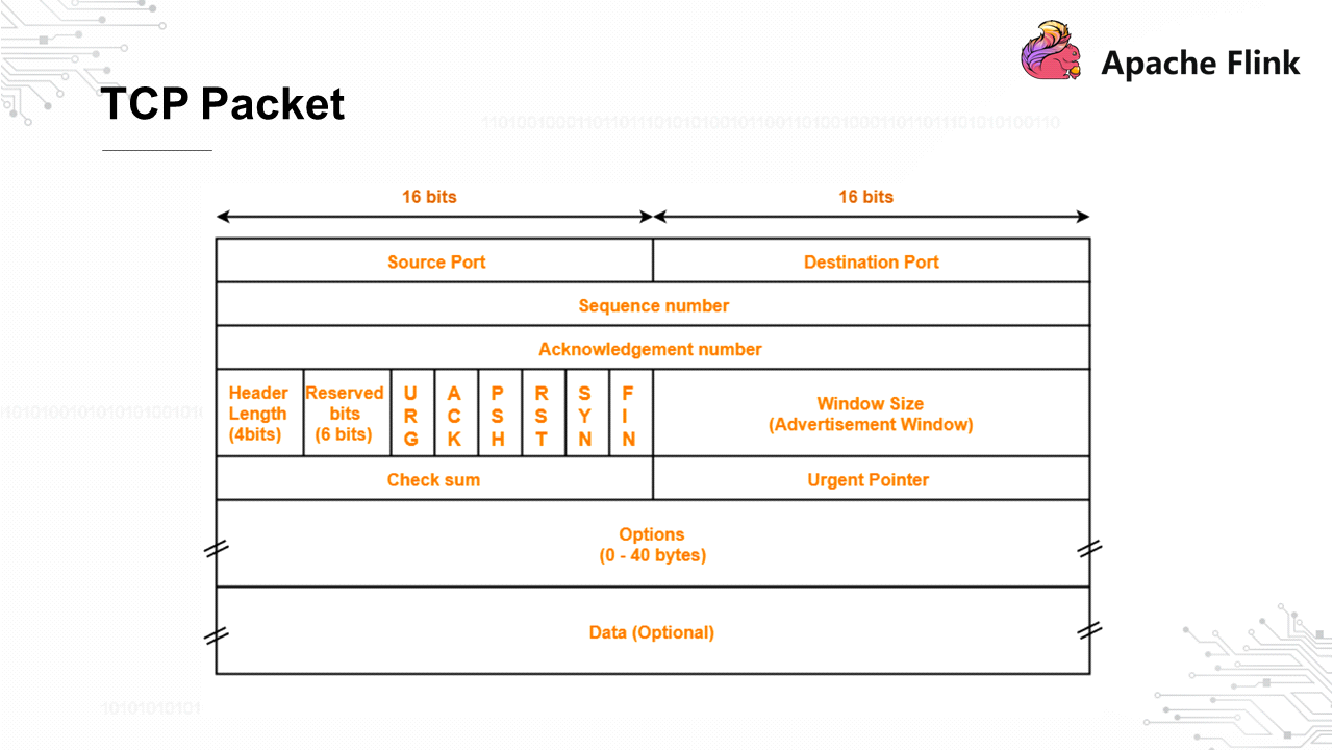
The following section describes the TCP-based flow control process.
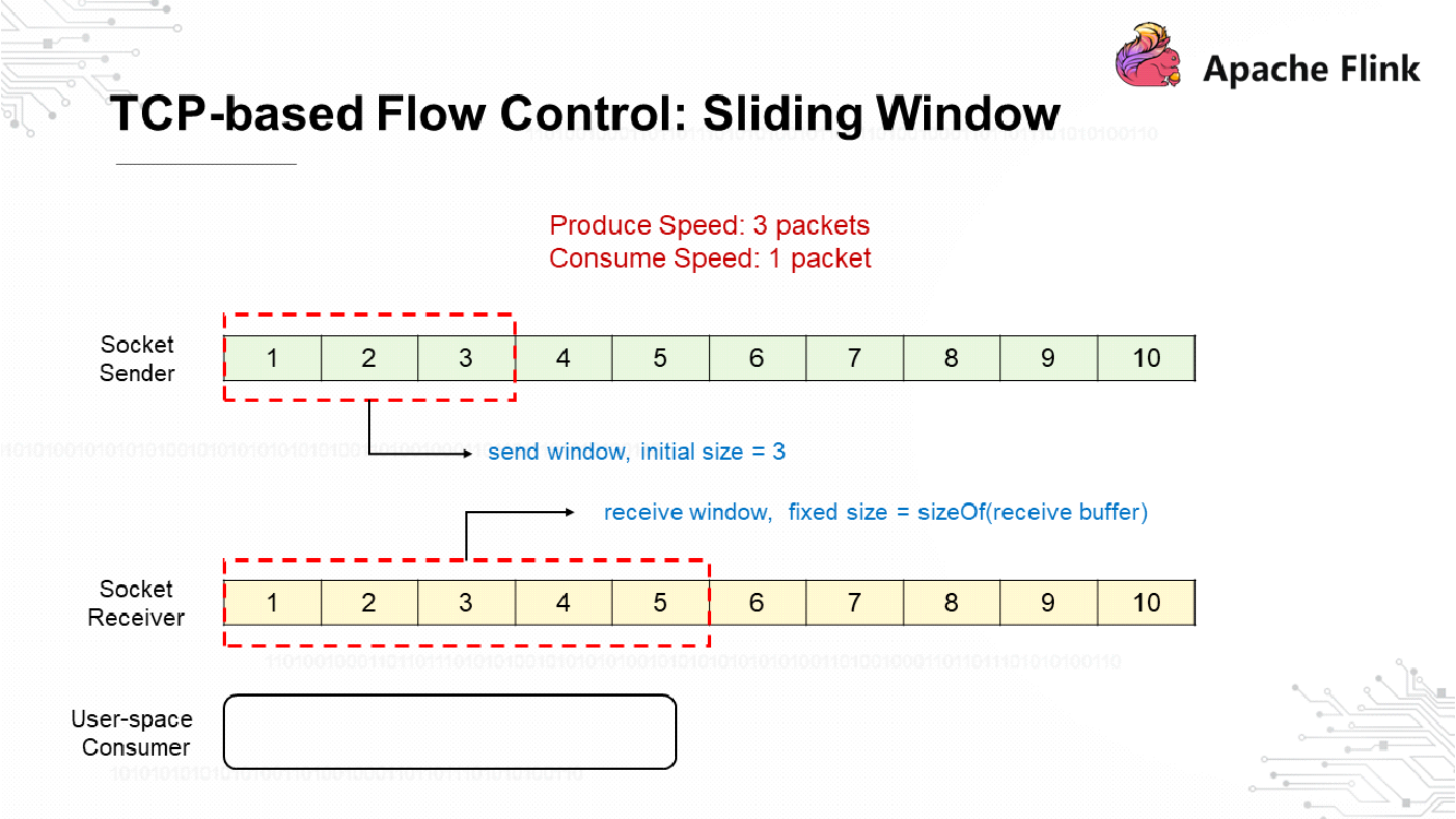
TCP-based flow control is implemented through a sliding window. The Socket sender sends data at a rate three times the rate at which the Socket receiver receives the data. Assume that the initial size of the send window is 3 and that the receive window has a fixed size. This implies the receive buffer has a size of 5.
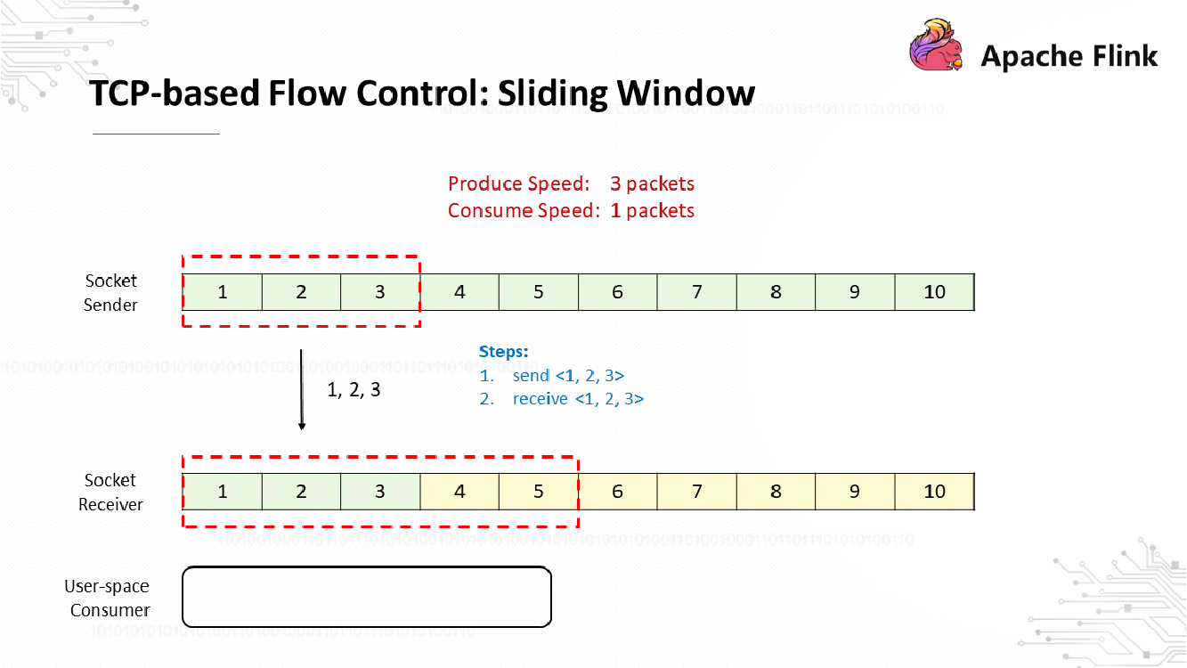
The Socket sender sends three packets at a time, which are numbered 1, 2, and 3, respectively. After receiving these packets, the Socket receiver buffers them.
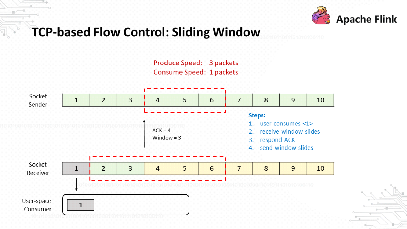
The Socket receiver consumes 1 packet at a time. Therefore, Packet 1 is consumed first and the receiver's sliding window moves forward by one position. Packets 2 and 3 are still in the buffers, and Buffers 4, 5, and 6 are empty. Therefore, the Socket receiver returns a response with an ACK number of 4 to ask the Socket sender to send packets with sequence numbers that start from 4. The Socket receiver sets its window size to 3, which is the same as the number of available buffers, while the other two buffers store Packets 2 and 3, respectively. After receiving the response from the Socket receiver, the Socket sender moves its sliding window forward to Positions 4, 5, and 6 in sequence.
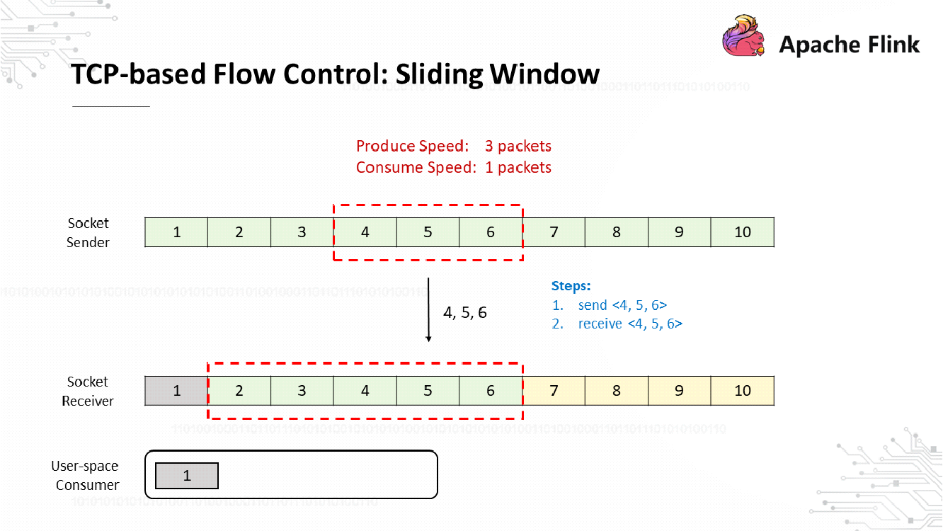
Then, the Socket sender sends the packets numbered 4, 5, and 6, respectively. After receiving these packets, the Socket receiver buffers them.
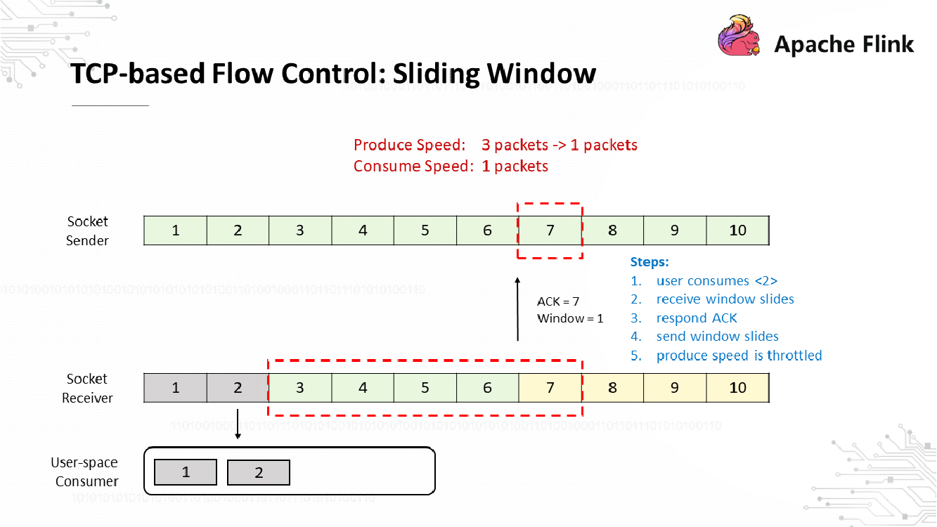
So far, the Socket receiver has consumed 2 packets and moved its sliding window forward by one position. Only one receive buffer is left available, so the Socket receiver returns a response that includes an ACK number of 7 and a window size of 1. After receiving the response, the Socket sender moves its sliding window forward by only one position instead of three because the Socket receiver's window size indicates that only one more packet can be received. Therefore, the Socket sender's sliding window moves to Position 7, and the transmit rate drops from 3 to 1.
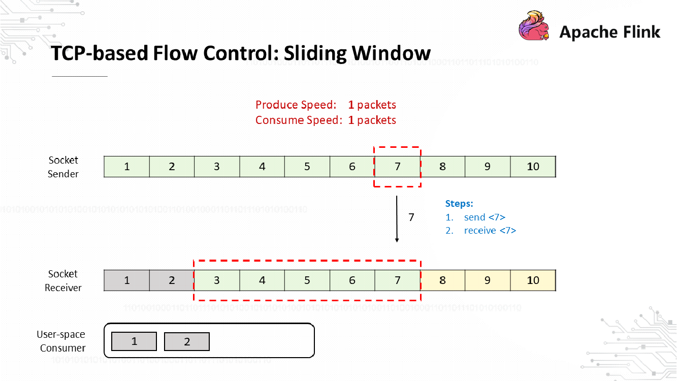
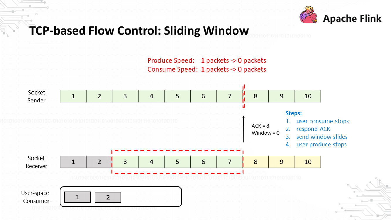
Next, the Socket sender sends a packet with a sequence number of 7. After receiving this packet, the Socket receiver fails to retrieve any packet from its buffers due to a consumption problem at the receiving end. Therefore, the Socket receiver returns a response with an ACK number of 8 and a window size of 0 to ask the Socket sender not to send any more data. As a result, the transmit rate drops to 0. At this time, the sender does not send any data, and the receiver does not provide any feedback, so how does the sender know when the consumer can resume consumption?
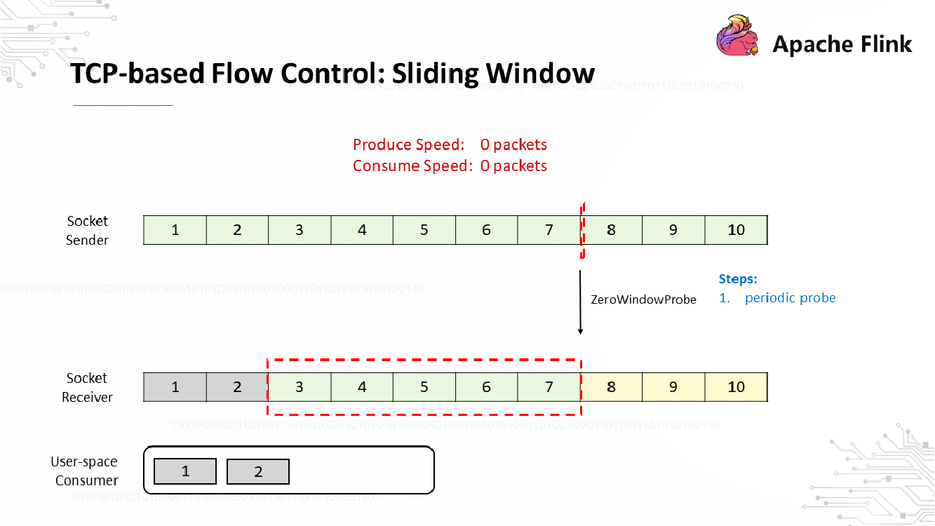
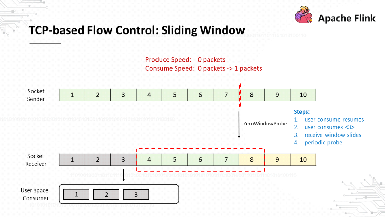
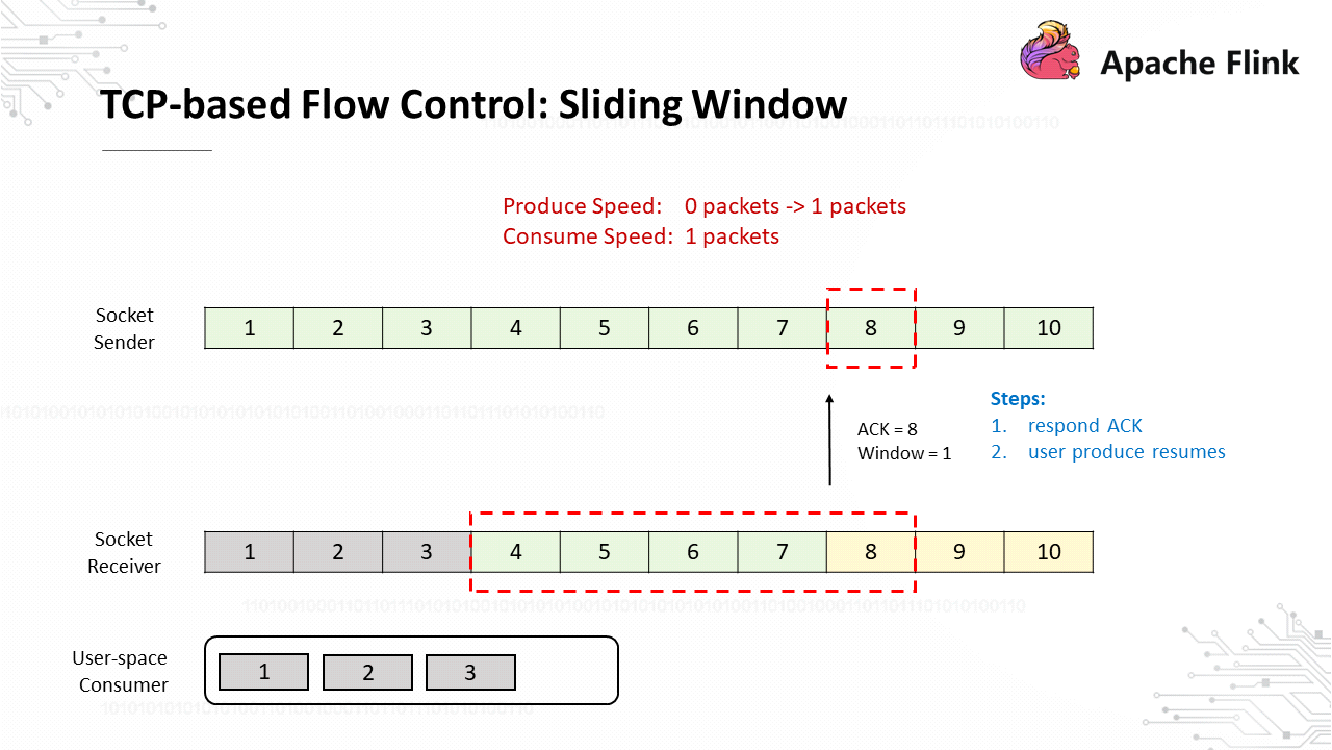
TCP implements ZeroWindowProbe in which the sender periodically sends a 1-byte probe message and the receiver returns its window size. After consumption is resumed at the receiving end and the receiver receives the probe message, the receiver sends its window size to the sender to resume data transmission. This completes the process of TCP-based feedback through a sliding window.
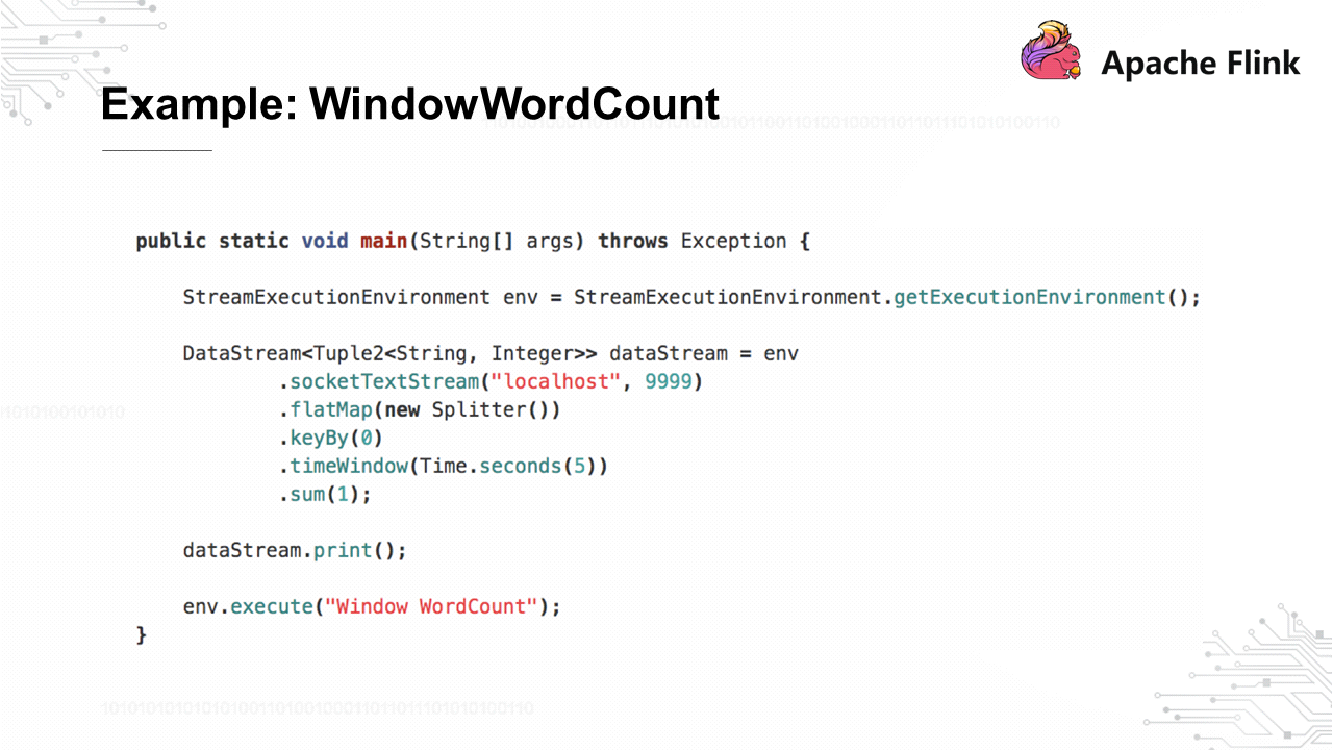
The general logic is to receive data from Socket, perform WordCount every 5 seconds, and start compilation after the code is submitted.
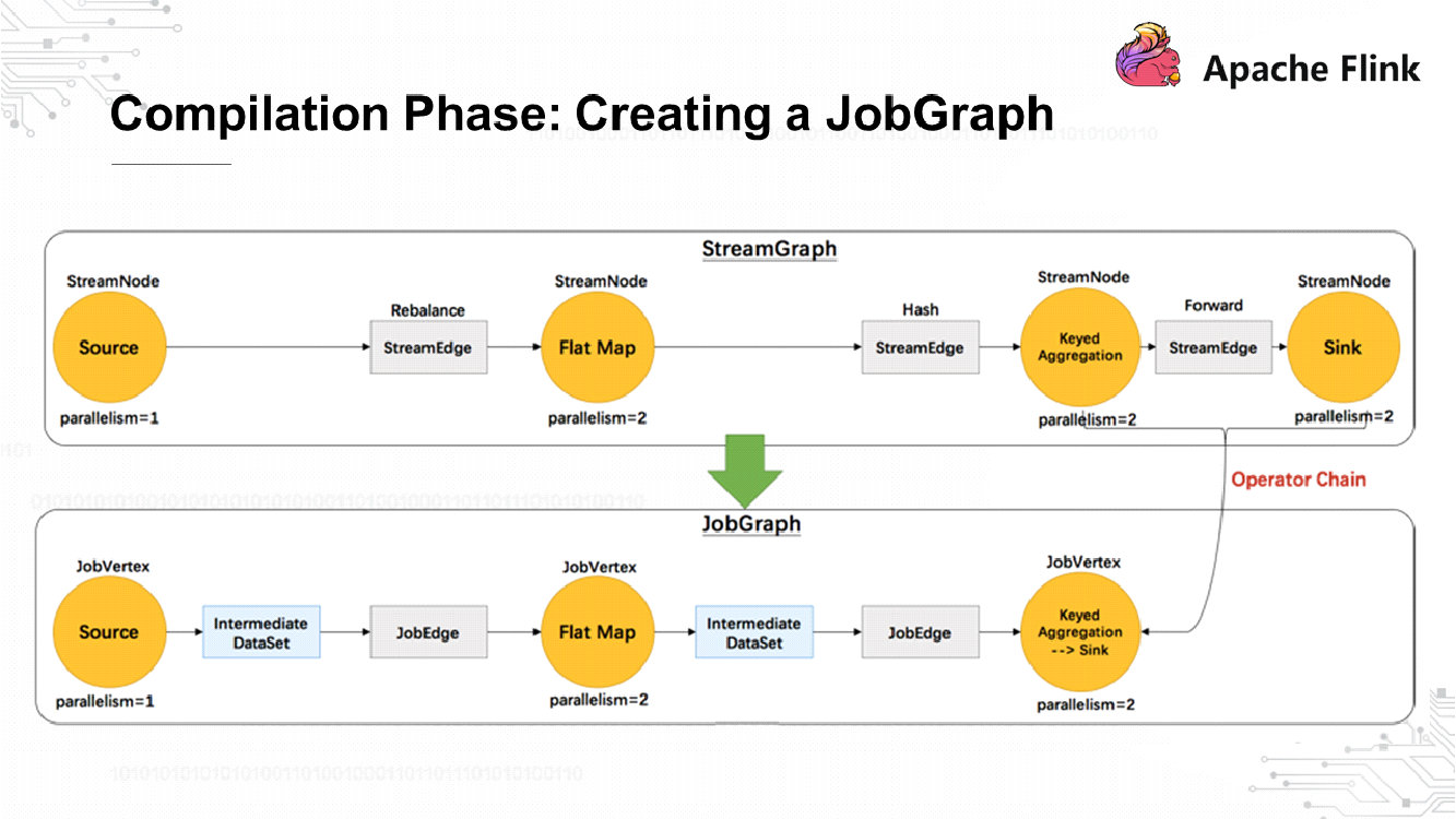
In the compilation phase, no jobs are submitted to the cluster. The client transforms the StreamGraph to a JobGraph, which is the most elementary unit for cluster submission. When a JobGraph is created, some optimizations are made to merge shuffle-free nodes. The created JobGraph is submitted to the client and the runtime phase starts.
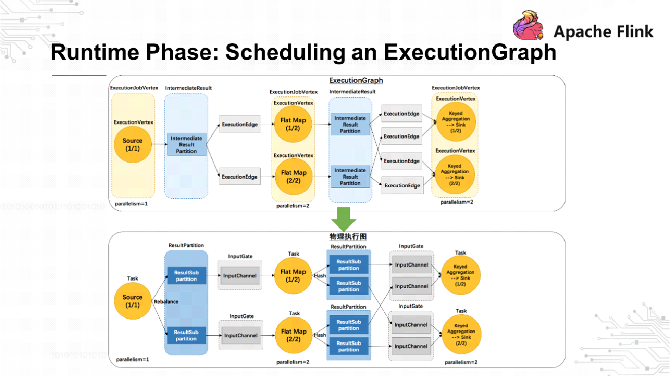
After the JobGraph is submitted to the cluster, an ExecutionGraph is created, which is the prototype of an execution task. Each task is divided into different subtasks. The IntermediateResultPartition module of the ExecutionGraph is used to send data, and the ExecutionGraph is sent to the JobManager's scheduler for scheduling. Conceptualize a physical execution graph as shown above. Each task receives data through an InputGate. The ResultPartition, which is located before the InputGate, is responsible for sending data. The ResultPartition is partitioned to maintain consistency with the downstream tasks. This forms a mapping between the ResultSubPartition and InputChannel. Based on this logical channel of network transmission, it's possible to break down the back pressure process.
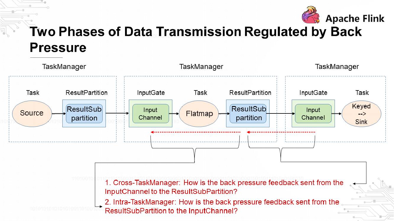
The data transmission process regulated by back pressure is divided into two phases and involves three TaskManagers. Each TaskManager includes a task, an InputGate for receiving data, and a ResultPartition for sending data. TaskManager is the most fundamental channel of data transmission. If the downstream task on a sink node is faulty, which slows down processing, how do we instruct the upstream task to lower its transmit rate accordingly? This question is broken down into two parts:
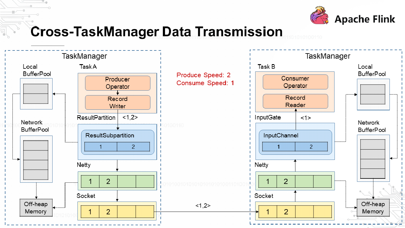
As mentioned earlier, data is sent by a ResultPartition, which is divided into ResultSubPartitions. Memory resources are managed by buffers.
A TaskManager has a network buffer pool that is shared by all tasks. During initialization, the network buffer pool applies for memory resources from the off-heap memory and synchronously manages these memory resources, which are released without using the Garbage Collection (GC) function of Java Virtual Machines (JVMs). With the network buffer pool, create a local buffer pool for each ResultSubPartition.
As shown in the preceding figure, the record writer of the left-side TaskManager writes two data records, which are numbered 1 and 2. The ResultSubPartition is empty during initialization and has no buffers to store the data records, so it applies for memory from the local buffer pool. The local buffer pool does not have enough memory, so it forwards the memory request to the network buffer pool, which applies for memory from the off-heap memory. The allocated memory is returned to the ResultSubPartition in reverse along the request path. Then, Data Records 1 and 2 are written to the ResultSubPartition. The buffers of the ResultSubPartition are copied to the Netty buffers and then to the Socket buffers before messages are sent. The messages are processed at the receive end in a way similar to how the messages are processed before sending. After processing, the messages can be consumed.
Next, let's simulate a scenario where the sender's rate (upstream) is 2 and the receiver's rate (downstream) is 1. The following section describes the back pressure process.
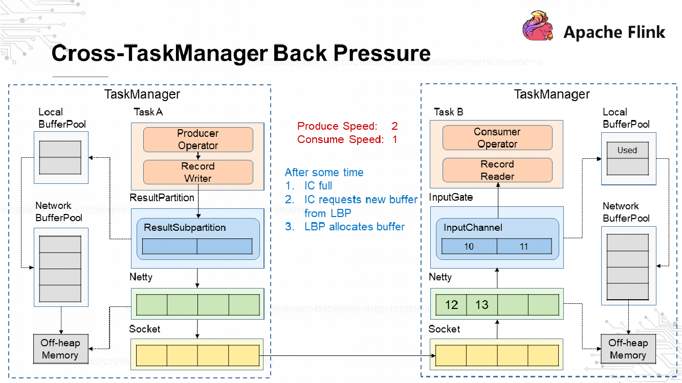
The InputChannel's buffers become exhausted after a time due to the rate mismatch between the sender and receiver. When this happens, the InputChannel applies for a new buffer from the local buffer pool. Then, a buffer in the local buffer pool is marked as Used.
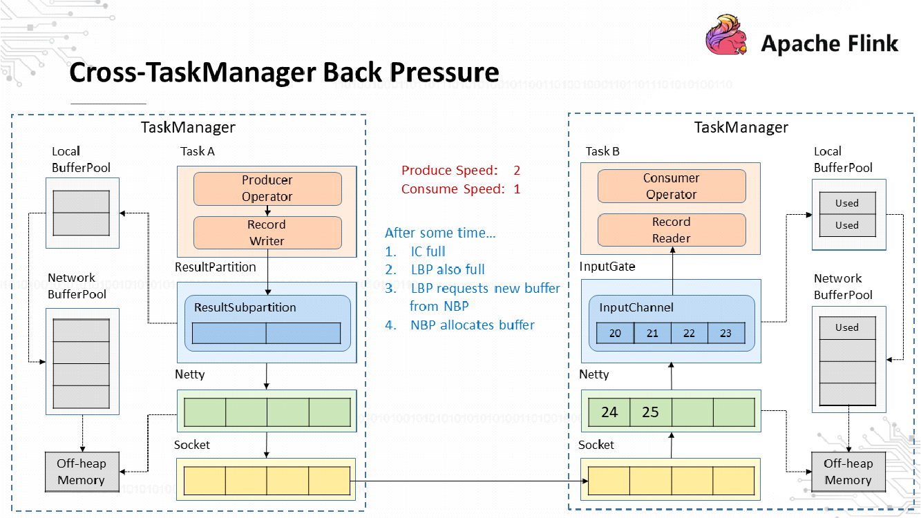
As the sender keeps sending data at a rate different from that of the receiver, the local buffer pool eventually runs out of buffers that can be allocated to the InputChannel. In this case, the local buffer pool applies for buffers from the network buffer pool. The maximum number of buffers that can be requested by each local buffer pool is limited to prevent a single local buffer pool from using up the buffers of the network buffer pool. The network buffer pool still has buffers that can be allocated to the local buffer pool.
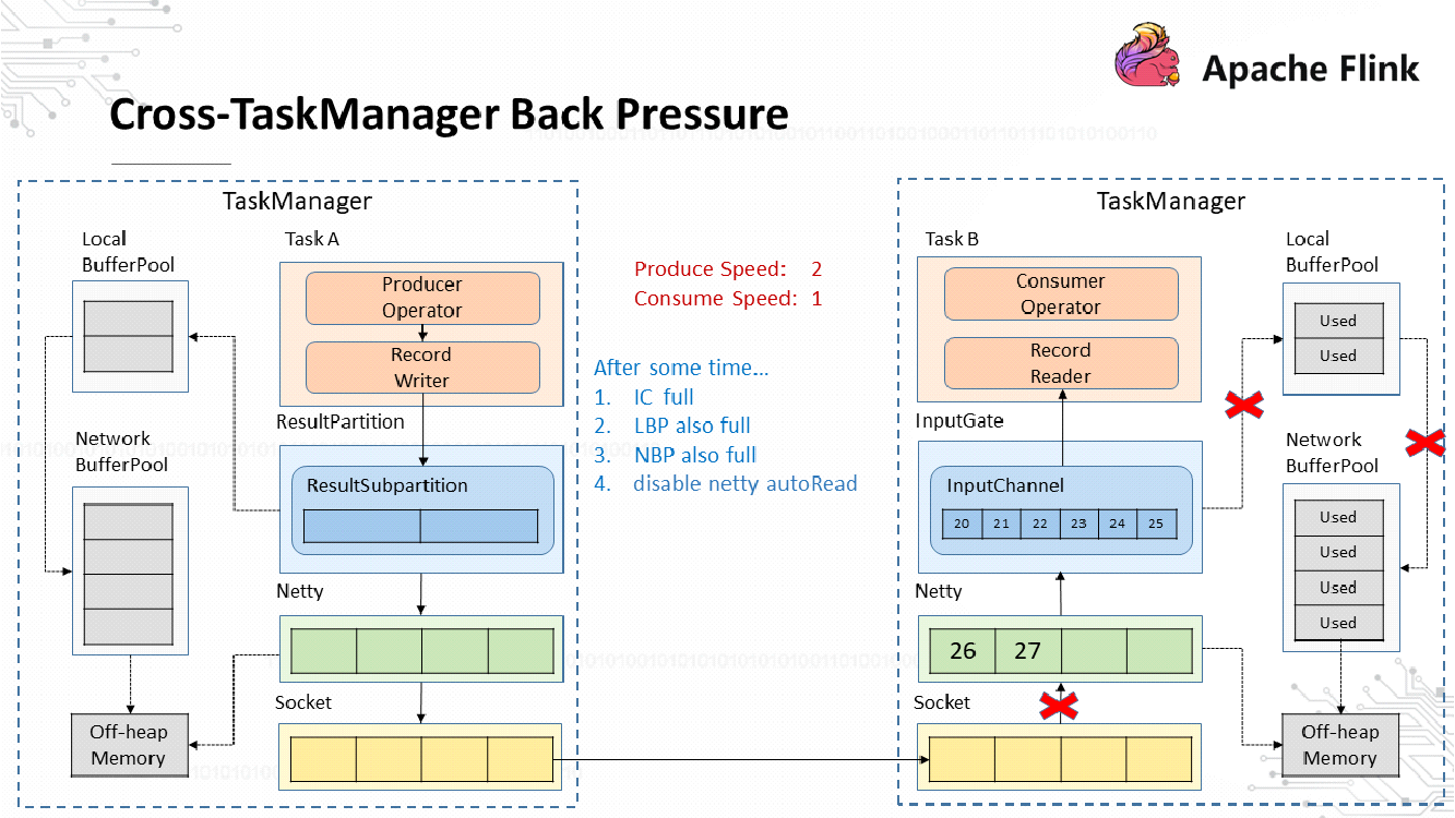
After a period of time, the network buffer pool will also be exhausted, or the local buffer pool will reach the buffer limit and cannot apply for any more buffers from the network buffer pool, causing a data read failure. In this case, Netty AutoRead is disabled and Netty no longer reads data from the Socket buffers.
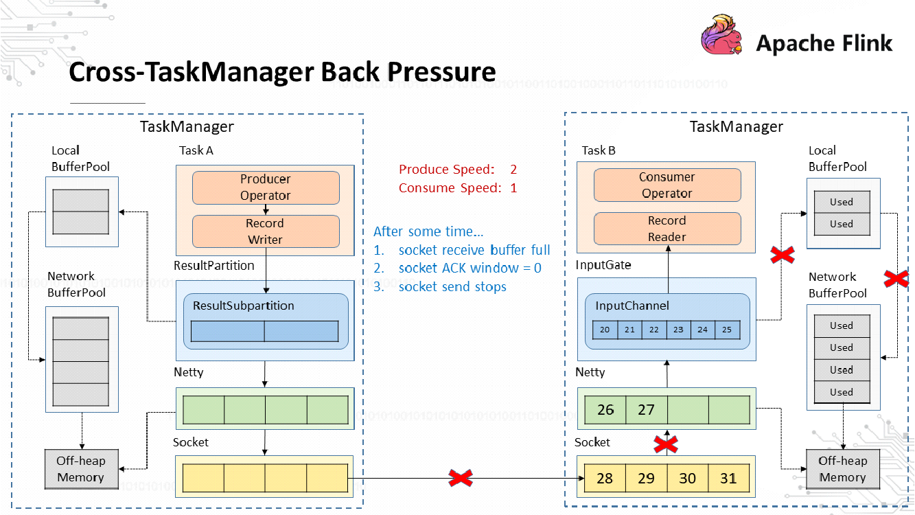
Soon the Socket buffers are also exhausted, and the receiver returns a response with a window size of 0 to the sender. This is due to the TCP-based sliding window mechanism. At this time, the Socket at the transmit end stops sending data.
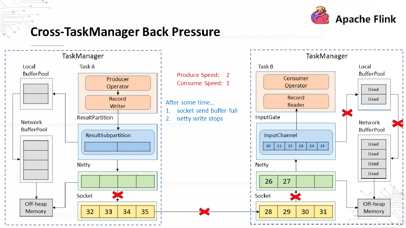
Soon the Socket buffers at the transmit end are also exhausted. When it detects this situation, Netty stops writing data to the Socket.
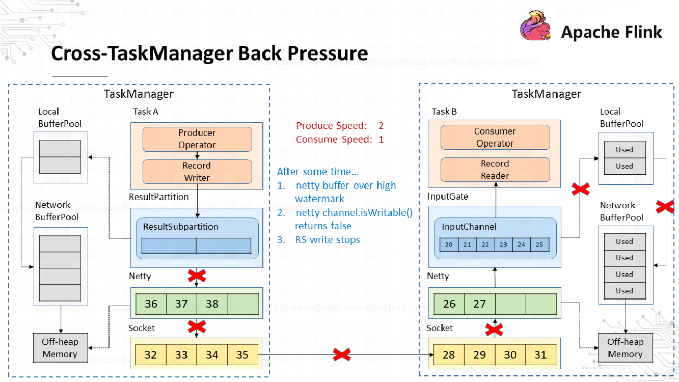
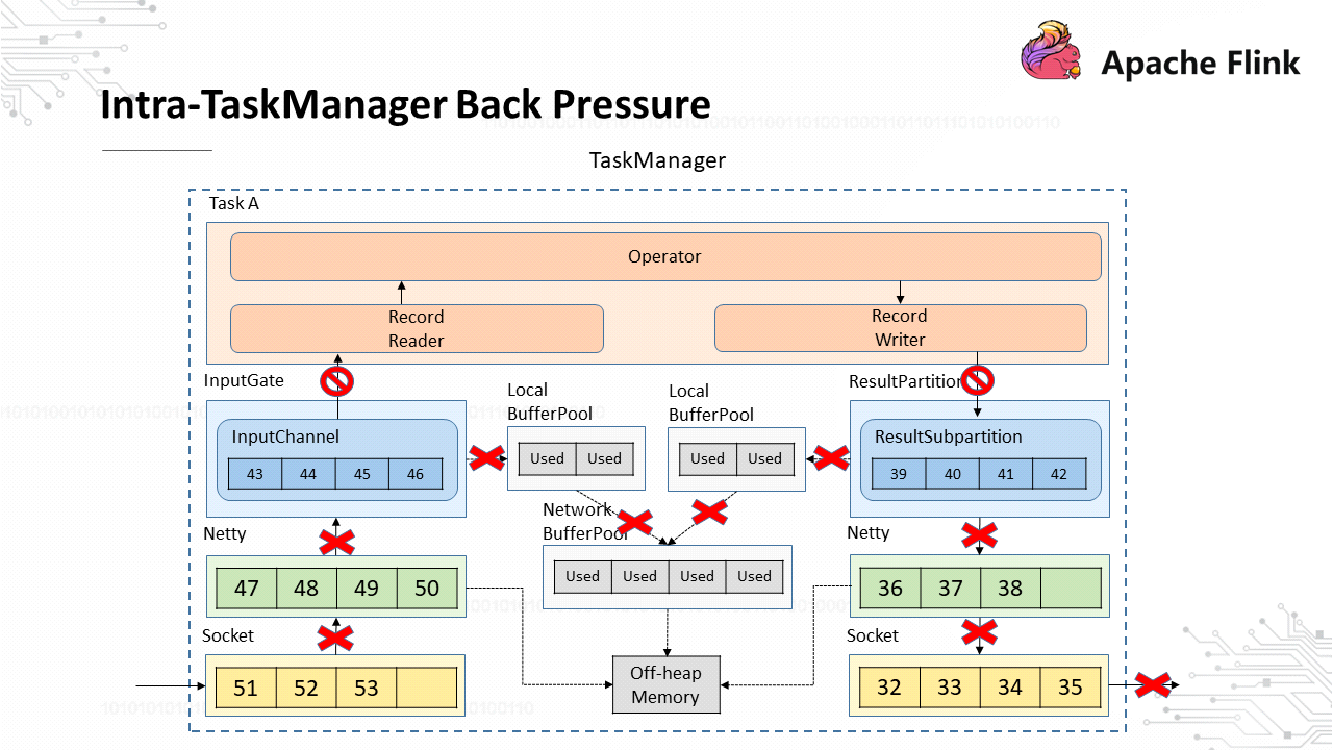
After Netty stops writing data to the Socket, data congestion occurs in the Netty buffers, which are unbounded. The maximum number of Netty buffers can be controlled using the high watermark of Netty's resource usage mechanism. When the high watermark is exceeded, Netty sets its channel to non-writable. When it detects a non-writable Netty, the ResultSubPartition stops writing data to Netty.
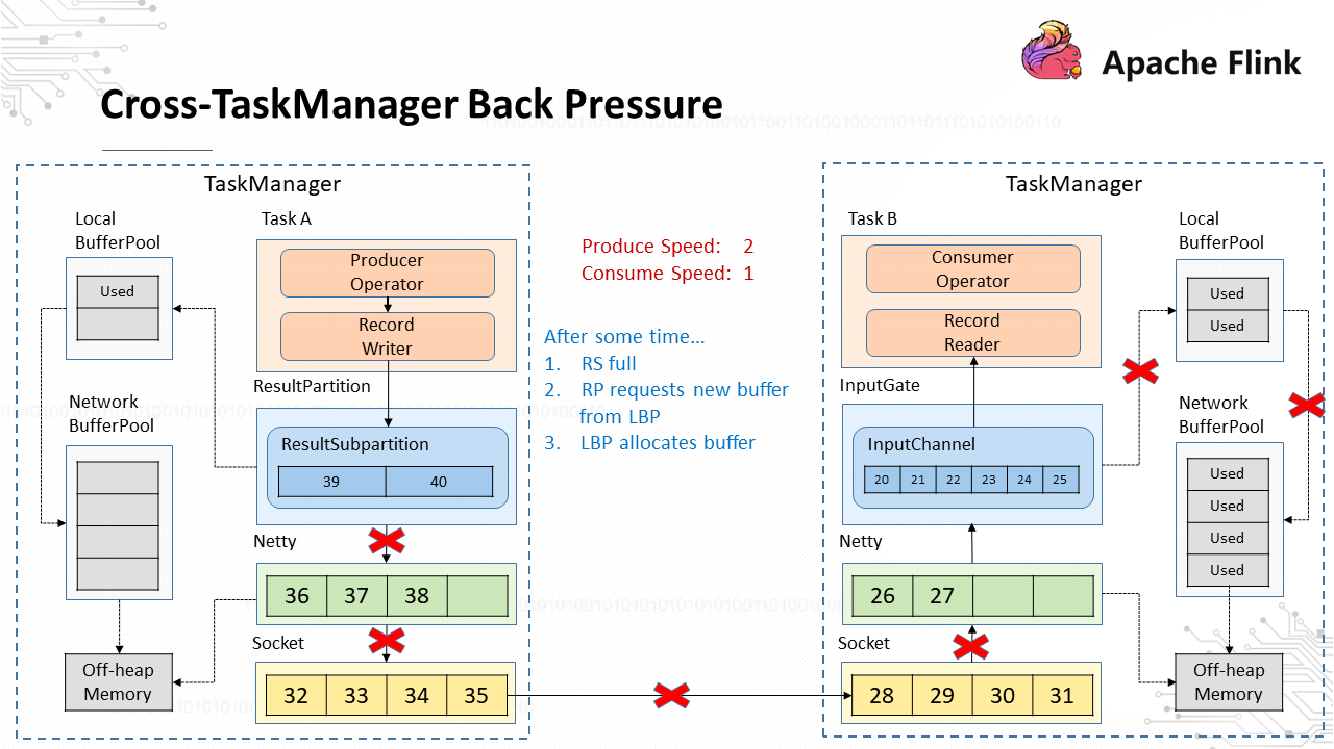
At this time, all loads are concentrated on the ResultSubPartition, which keeps applying for memory from the local buffer pool and network buffer pool.
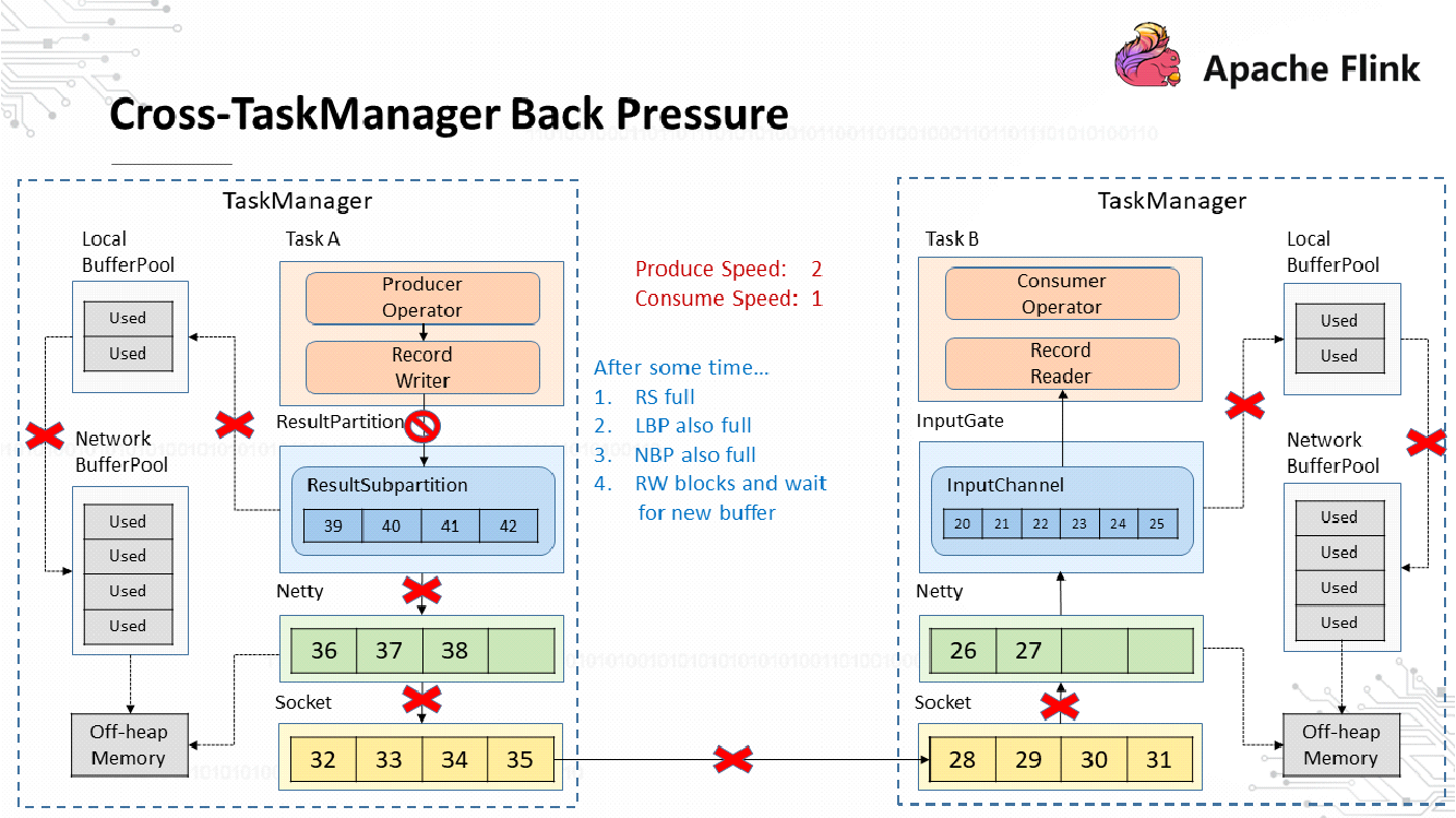
When both the local buffer pool and network buffer pool are exhausted, all operators stop writing data. This completes the process of cross-TaskManager back pressure.
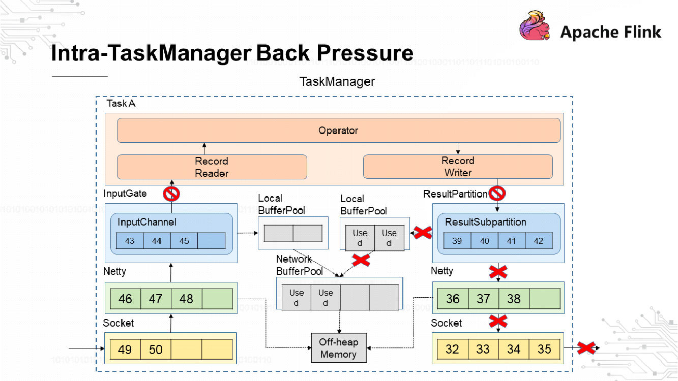
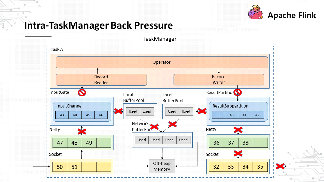
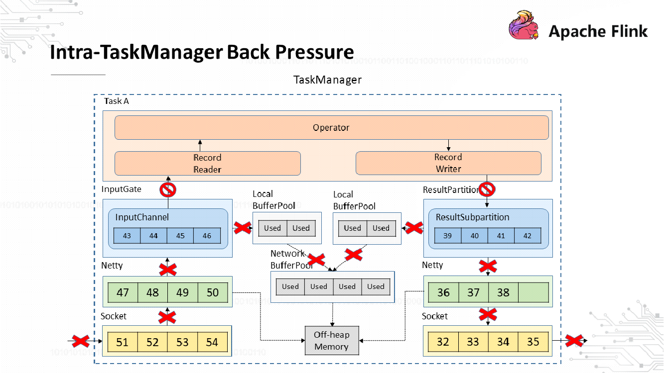
When back pressure occurs on the downstream TaskManager, the ResultSubPartition of the upstream TaskManager stops writing data and the record writer is blocked. The blocking is due to the fact that the input and output of the operator are executed by the same thread. The record reader stops reading data from the InputChannel after the record writer is blocked, while the upstream TaskManager keeps sending data, which eventually consumes all its buffers. The following figure shows the back pressure process within a TaskManager.
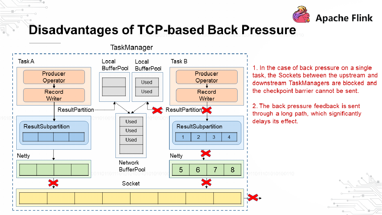
Before turning to credit-based back pressure on Flink, let's analyze the disadvantages of TCP-based back pressure.
Flink implements credit-based back pressure in a way similar to how back pressure is implemented during TCP-based flow control, but without the disadvantages of the latter. The use of credits is similar to the sliding window mechanism in TCP.
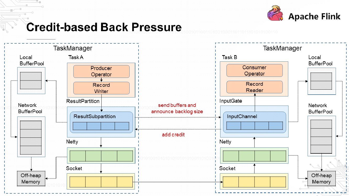
The preceding figure shows the back pressure process on Flink. Before sending messages to the InputChannel, the ResultSubPartition sends a backlog size to inform the downstream TaskManager of how many messages will be sent. The downstream TaskManager calculates the number of buffers required to store these messages. If it has sufficient buffers, the downstream TaskManager returns a credit to ask the upstream TaskManager to send messages. The dashed lines between the ResultSubPartition and InputChannel indicate communication over Netty and Socket. Consider the following example.
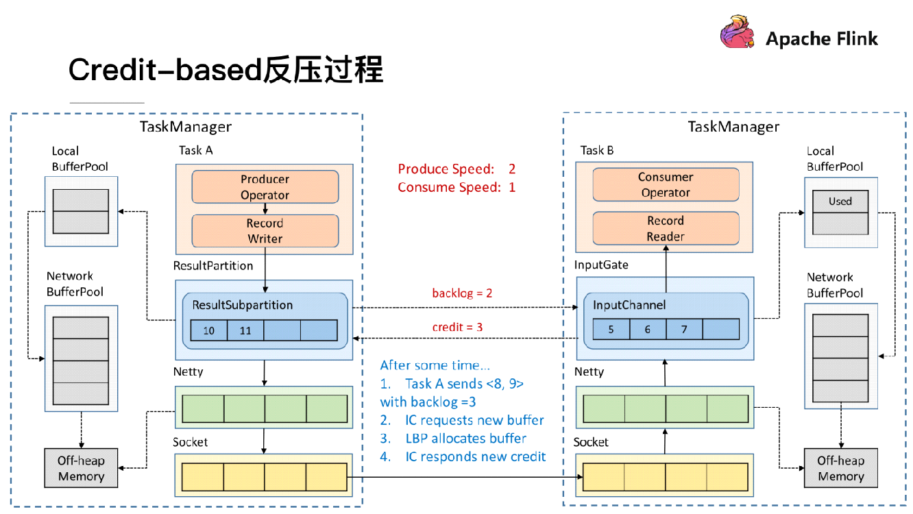
Assume that the upstream and downstream rates do not match, with the upstream transmission rate being 2 and the downstream receiving rate being 1. As shown in the preceding figure, the ResultSubPartition needs to send two messages, Message 10 and Message 11, so its backlog size is 2. In this case, the ResultSubPartition sends Message 8 and Message 9 along with a backlog size of 2 to the downstream TaskManager. After receiving the backlog size, the downstream TaskManager determines whether it has two available buffers to store the two messages that the upstream TaskManager will send. If the InputChannel does not have two available buffers, it applies for buffers from the local buffer pool and network buffer pool, which then allocate the requested buffers.
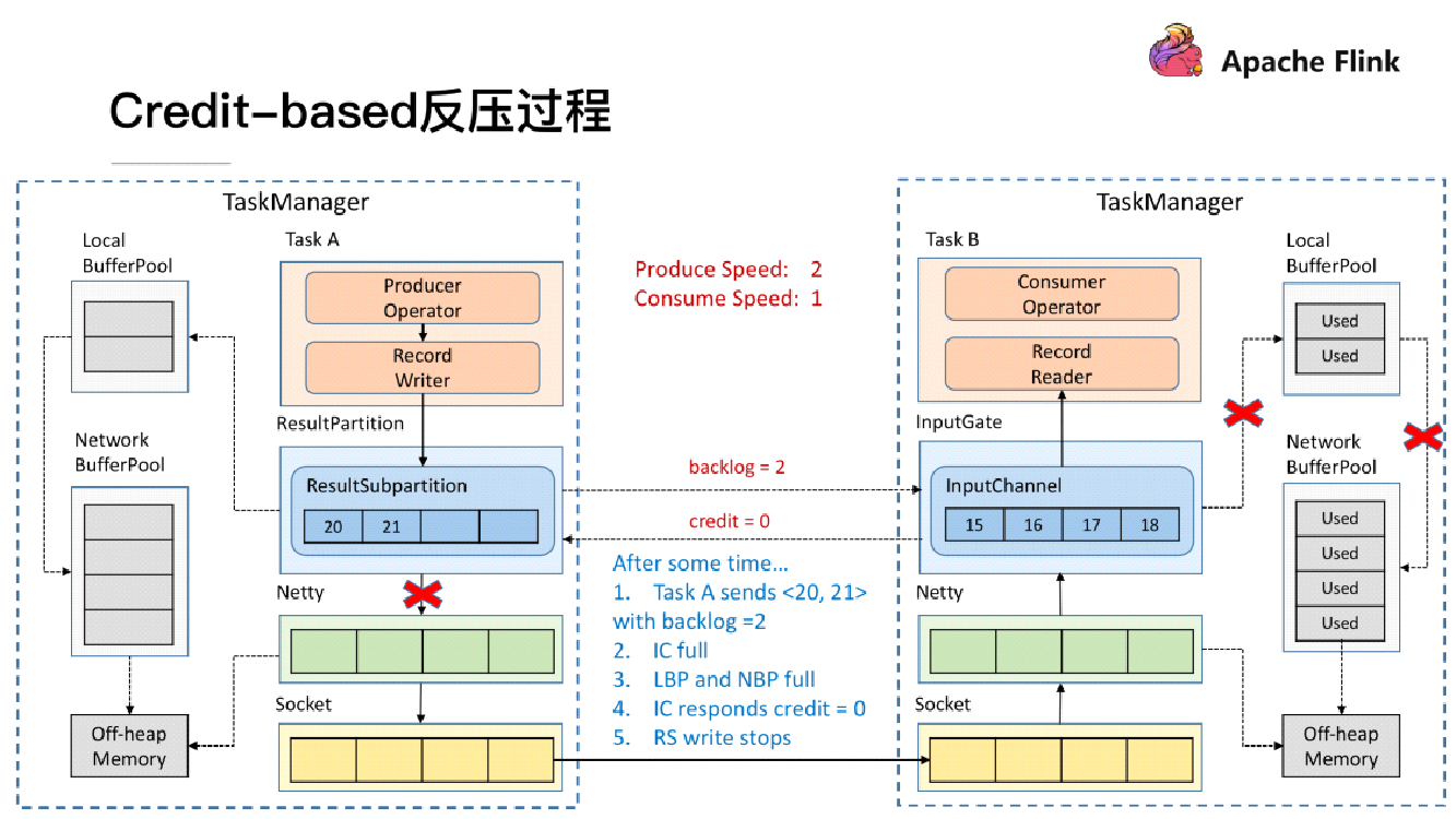
After a certain period of time, the downstream TaskManager reaches the buffer limit due to the mismatch between the upstream transmit rate (2) and the downstream receive rate (1). In this case, the downstream TaskManager returns a credit of 0 to the upstream TaskManager. After receiving this credit, the ResultSubPartition stops sending data to Netty, and the buffers of the upstream TaskManager will soon be exhausted. This achieves the effect of back pressure. The ResultSubPartition can perceive back pressure by itself, without waiting for feedback from the Socket and Netty. This ensures that back pressure takes effect more quickly. The use of credits avoids the problem of blocking the Sockets between the upstream and downstream TaskManagers when back pressure occurs on a single task.
When dynamic back pressure is used, do we still need static rate-limiting?
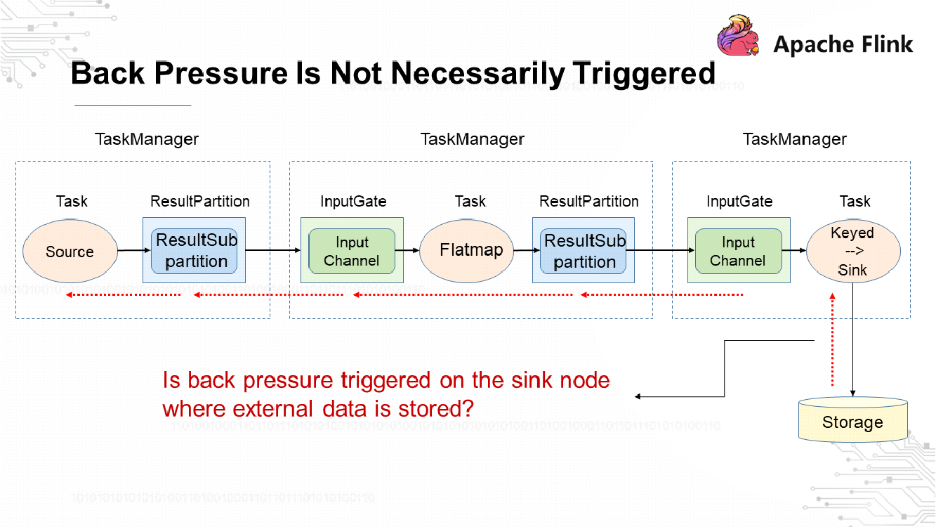
Dynamic back pressure cannot solve all problems. The results of stream computing are output to external storage. As a result, back pressure is not necessarily triggered on the sink nodes where external data is stored depending on the implementation method of external storage. Message-oriented middleware capable of flow control and rate-limiting, such as Kafka, may send back pressure feedback to sink nodes through a protocol. However, Elasticsearch cannot send back pressure feedback to sink nodes. To prevent external storage from being crushed under a massive amount of data, implement static rate-limiting at the source end. Therefore, we need to determine whether to use dynamic back pressure or static rate limiting based on the actual scenario.
Flink Checkpoints Principles and Practices: Flink Advanced Tutorials
In-depth Analysis of Flink Job Execution: Flink Advanced Tutorials

206 posts | 54 followers
FollowAlibaba EMR - October 12, 2021
Apache Flink Community China - December 25, 2019
Apache Flink Community China - August 8, 2022
Alibaba Cloud Native Community - January 6, 2023
Alibaba Cloud MaxCompute - January 22, 2021
Apache Flink Community China - December 25, 2020

206 posts | 54 followers
Follow Realtime Compute for Apache Flink
Realtime Compute for Apache Flink offers a highly integrated platform for real-time data processing, which optimizes the computing of Apache Flink.
Learn More Message Queue for Apache Kafka
A fully-managed Apache Kafka service to help you quickly build data pipelines for your big data analytics.
Learn More Super App Solution for Telcos
Alibaba Cloud (in partnership with Whale Cloud) helps telcos build an all-in-one telecommunication and digital lifestyle platform based on DingTalk.
Learn More Media Solution
An array of powerful multimedia services providing massive cloud storage and efficient content delivery for a smooth and rich user experience.
Learn MoreMore Posts by Apache Flink Community