By Gao Yun
This article describes the core mechanism of running jobs in Flink Runtime. It provides an overview of the Flink Runtime architecture, basic job running process, and describes how Flink manages resources, dispatches jobs, and recovers from failure during the process. Also, it focuses on some ongoing work in the Flink Runtime layer.
Figure 1 shows the overall architecture of the Flink. Flink runs in various environments. For example, running directly in single-process and multi-thread mode to enable debugging. It also runs in resource management systems, such as YARN and k8s, as well as in a variety of Cloud environments.
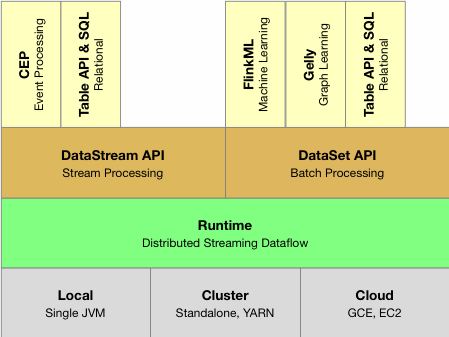
Figure 1. Flink Architecture: Runtime layer provides a unified distributed execution engine targeting different execution environments.
For different execution environments, Flink provides a unified distributed job execution engine-Flink Runtime. In the Runtime layer, Flink provides two APIs-DataStream for writing stream jobs, and DataSet for writing batch jobs, as well as a set of more advanced APIs to simplify the process of writing specific jobs.
Figure 2 shows the architecture of Flink Runtime, where the basic structure of a Flink cluster is provided. The overall architecture of Flink Runtime is mainly implemented in FLIP-6. Generally, it has the standard master-slave architecture, where the left-side white box represents the master managing resources and jobs in the cluster. The two TaskExecutors on the right are slaves that provide specific resources and run jobs.
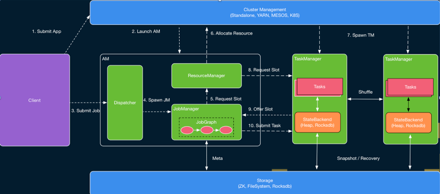
Figure 2. The basic architecture of the Flink cluster. The Flink Runtime adopts the standard master-slave architecture.
A master consists of three components-Dispatcher, ResourceManager, and JobManager. The Dispatcher receives jobs from users and starts a new JobManager component for individual newly submitted jobs. The ResourceManager (only one in a Flink cluster) manages resources. The JobManager is responsible for managing job execution. Multiple jobs can run simultaneously in a Flink cluster, each having its own JobManager. All three components are included in the AppMaster process.
In this architecture, when a user submits a job, the script starts a Client process to compile and submit the job. It compiles the code written by the user into a JobGraph. During this process, it also performs checks and optimization. For example, to determine which Operators can be chained to the same task. Then, the Client submits the JobGraph to the cluster, so the JobGraph can run there. At this point, two modes are available: Session mode is like Standalone. AM is started in advance, and the Client directly connects to the Dispatcher and submits the job; and Per-Job mode, under which AM is not started in advance, and the Client first requests resources from resource management systems, such as YARN and k8s, to start the AM and then submits the job to the Dispatcher in the AM.
When the job is submitted to the Dispatcher, the Dispatcher starts a JobManager, which then requests resources from the ResourceManager to start specific tasks in the job. The TaskExecutor may or may not have been started, depending on which mode is used. If the Session mode is used, the ResourceManager already has resources that the TaskExecutor registered at this time and you can directly select idle resources for allocation. Otherwise, the ResourceManager needs to request resources from external resource management systems to start the TaskExecutor and wait for the TaskExecutor to register corresponding resources before idle resources are selected and allocated. Currently, the resources of the TaskExecutor in Flink are described by slots.
A slot generally runs a specific task. However, in some specific scenarios, a slot can also run multiple associated tasks (this will be detailed later in this article). After the ResourceManager selects an idle slot, it informs the corresponding task manager (™) to assign the slot to JobManager XX. After the TaskExecutor completes the recording process, it registers the slot to the JobManager. When the JobManager receives the slot registered by the TaskExecutor, the task can be submitted.
Once the TaskExecutor receives the task submitted from the JobManager, a new thread is started to run this task. After starting the task, pre-defined computations are performed, and data is exchanged through the Data Shuffle module.
That is the basic process of running a job in the Flink Runtime layer. Flink supports two different modes: Per-job and Session. In Figure 3, Per-Job mode is when a Flink cluster only runs a single job; each job has its own Dispatcher and ResourceManager. Additionally, in Per-Job mode, both AppMasters and TaskExecutors are requested on demand.
Therefore, Per-job is more suitable for running large jobs that take a long time, have high-stability requirements and are not sensitive to the resource application time. In contrast, Session mode is when Flink pre-starts the AppMaster and a set of TaskExecutors to run multiple jobs throughout the cluster’s life cycle. Therefore, Session mode is more suitable for running small jobs that don't take much time.
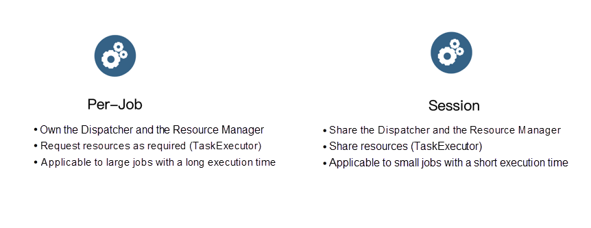
Figure 3. Flink Runtime supports two execution modes: Per-Job and Session.
This section provides more details about resource management and job dispatching in Flink. In fact, job dispatching can be seen as the process of matching resources with tasks. As mentioned in the preceding section, resources are represented by slots in Flink, and each slot can be used to run different tasks. Meanwhile, tasks (specific tasks in a job) contain the user logic to be executed. The main goal of dispatching is to find a matching slot for a specific task. Logically, each slot requires a vector to describe the number of various resources that it provides and the number of various resources that each task requires should be defined.
However, before version 1.9, Flink did not support fine-grained resource descriptions. Instead, Flink considered the amount of the resources provided by each slot is the same as that required for each task. Starting with Flink 1.9, support for fine-grained resource matching has been added. However, this feature is currently under improvement.
Job dispatching is based on resource management. Let's look at the implementation of resource management in Flink. As mentioned before, resources in Flink are represented by slots in TaskExecutors. In Figure 4, the ResourceManager has a sub-component called, SlotManager, which maintains the information and status of slots in all TaskExecutors of the current cluster. For example, which TaskExecutor a specific slot belongs to and whether that slot is idle.
When the JobManager applies for resources for a specific task, the ResourceManager may request resources to start new TaskExecutors, depending on whether you are in Per-Job or Session mode. After the TaskExecutor starts, it finds currently active ResourceManagers and performs the registration.
The registration information contains information about all the slots in the TaskExecutor. When the ResourceManager receives the registration information, the SlotManager records the slot information. When the JobManager requests resources for a task, the SlotManager selects one from currently idle slots in accordance with certain rules and begins the allocation. After the allocation is done, as mentioned in the second section, the RM sends RPCs to the TaskManager, asking the selected slot to be assigned to a specific JobManager.
If the TaskManager has not performed a task from the JobManager, it needs to connect to the JobManager before sending the RPC request that provides a slot. In the JobManager, all task requests are cached in the SlotPool. When a slot is provided, the SlotPool selects the corresponding request from cached requests and ends the corresponding request process.
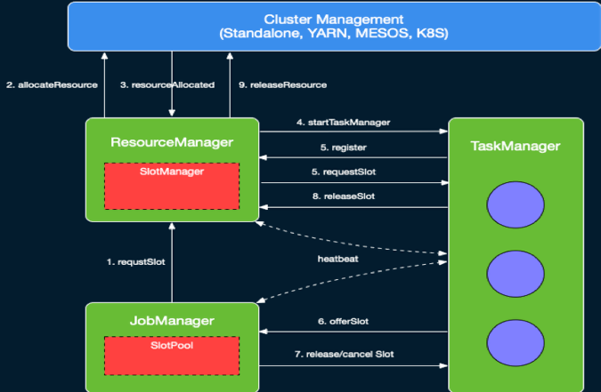
Figure 4. Interactions between resource management modules in Flink.
When a task ends, the JobManager is notified whether the corresponding end status is normal or abnormal. Then, the slot is marked as Occupied But Not Executed on the TaskManager side. The JobManager caches corresponding slots to the SlotPool but does not release them immediately. This avoids the problem that occurs when the slot directly returns to the ResourceManager, and a new slot applies immediately when the task needs to be restarted due to an abnormal ending. Through delayed-release, the tasks to be failed over can be dispatched back to the original TaskManager as soon as possible to speed up the failover process.
When a slot cached in the SlotPool has not been used for the specified time, the SlotPool releases the slot. Like the process of applying for a slot, the SlotPool informs the TaskManager to release the slot, and then the TaskExecutor notifies the ResourceManager that the slot has been released. The release logic is finally completed.
In addition to the normal communication logic, scheduled heartbeat messages are available between the ResourceManager and the TaskExecutor to synchronize the status of slots. In a distributed system, the loss and disorder of messages are inevitable. These problems may cause inconsistency in the components of the distributed system.
Without scheduled messages, the components cannot be recovered from these inconsistent statuses. In addition, if a component does not receive a heartbeat from the other component for a long time, the corresponding component is considered invalid and enters the failover process.
Based on slot management, Flink dispatches tasks to corresponding slots. As mentioned earlier, Flink has not yet fully introduced fine-grained resource matching. By default, each slot is allocated to one task. However, this may lead to low resource utilization in some cases. As Figure 5 shows if A, B, and C execute the computational logic in sequence, allocating separate slots to A, B, and C leads to a low resource utilization rate. To solve this problem, Flink provides the Share Slot mechanism.
As shown in Figure 5, based on Share Slot, multiple tasks from different JobVertex can be deployed in each slot, but tasks from the same JobVertex cannot be deployed. In Figure 5, at most, one task from A, B, or C can be deployed in each slot, but one task from A, B, and C can be deployed simultaneously. If a single task occupies fewer resources, Share Slot can improve resource utilization. Share Slot also provides a simple way to maintain load balancing.
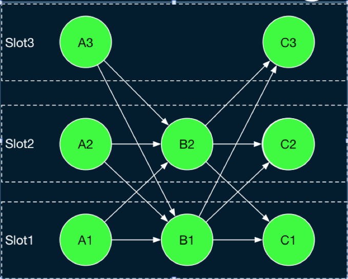
Figure 5. With Flink Share Slot, multiple tasks from different JobVertex can be deployed in each slot.
Based on the preceding slot management and allocation logic, the JobManager maintains the task execution status in a job. As previously mentioned, the client submits a JobGraph, which represents the logical structure of the job, to the JobManager. The JobManager expands the JobGraph concurrently to obtain the key ExecutionGraph in the JobManager. The structure of ExecutionGraph is shown in Figure 6. Compared with the JobGraph, corresponding objects are created in the ExecutionGraph for each task and intermediate results, so that the information and status of these entities can be maintained.
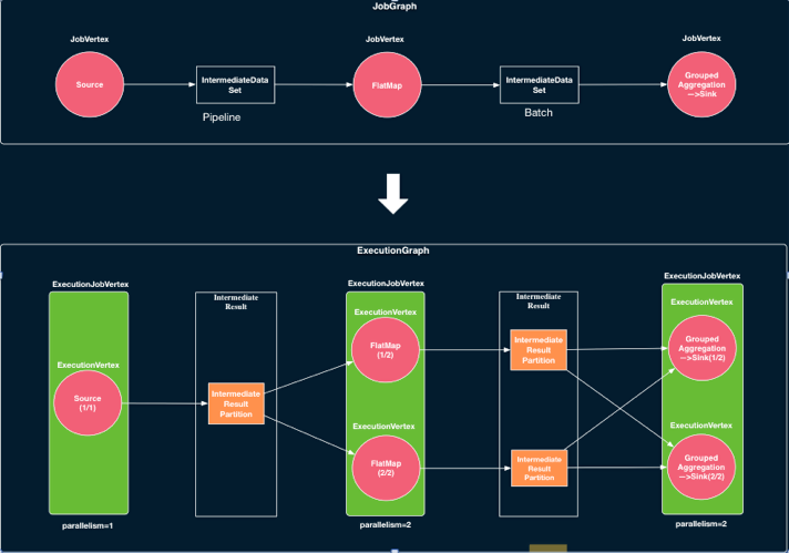
Figure 6. JobGraph and ExecutionGraph in Flink.
The ExecutionGraph is formed by expanding the JobGraph concurrently and serves as the JobMaster core data structure.
A Flink job contains multiple tasks. Therefore, another key problem is the order in which tasks are dispatched in Flink. As shown in Figure 7, Flink currently provides two types of basic dispatching logic: Eager Dispatching and Lazy_From_Source. Eager Dispatching, as its name implies, requests resources to dispatch all tasks when the job starts. This dispatching algorithm is mainly used to dispatch streaming jobs that may not have been terminated.
Accordingly, Lazy_From_Source starts from the source and dispatches jobs in topological order. Simply put, Lazy_From_Source dispatches source tasks that do not have upstream tasks. When these tasks are completed, it caches the output data to the memory or writes it to the disk. Then, for subsequent tasks, when all precursor tasks are completed, Flink dispatches these tasks. These tasks perform their own computations by reading the cached output data upstream. This process continues until all tasks are completed.
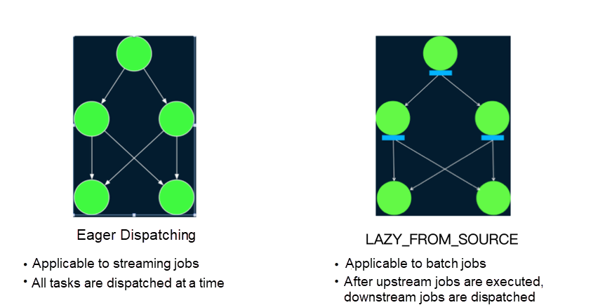
Figure 7. Two basic dispatching policies in Flink: Eager Dispatching applies to streaming jobs, while Lazy_From_Source applies to batch jobs.
During the execution of a Flink job, in addition to the normal execution process, errors may occur for various reasons, such as the environment. Generally, errors may be classified into two categories: errors in task execution or errors in the master of the Flink cluster. As errors are inevitable, to improve availability, Flink needs to provide an automatic error recovery mechanism to retry.
Flink provides a variety of error recovery policies for task execution errors. As shown in Figure 8, the first policy is Restart-all, which means that all tasks are restarted directly. For streaming tasks, Flink provides a Checkpoint mechanism. After a task is restarted, it can be directly executed from the last Checkpoint. Therefore, this is more suitable for streaming jobs. The second error recovery policy is Restart-individual, which applies only when no data transmission exists between tasks. In this case, you can directly restart the faulty task.
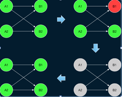
Figure 8. An example of the Restart-all error recovery policy. This policy directly restarts all tasks.
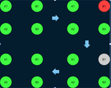
Figure 9. An example of the Restart-individual error recovery policy.
This policy applies only to jobs that do not require data transmission between them. For such jobs, you can only restart tasks with errors.
Flink does not provide the Checkpoint mechanism for batch jobs. Therefore, for jobs that require data transmission between them, restarting all tasks directly may cause jobs to be computed from scratch and cause certain performance problems. To enhance failover for batch jobs, Flink 1.9 introduced a new region-based failover policy. In a Flink batch job, two types of data transmission are available between tasks Pipeline type, in which the upstream and downstream tasks directly transmit data through the network, so the upstream and downstream tasks need to run simultaneously; and Blocking type (as previously described), in which the upstream tasks cache the data, so the upstream and downstream tasks can be executed separately.
Based on these two types of transmission in Flink, the subgraph of the task that uses the Pipeline mode in the ExecutionGraph to transmit data is known as a region. Therefore, the entire ExecutionGraph is divided into multiple subgraphs. Tasks in a region must be restarted at the same time. However, a blocking edge exists at the region boundary for tasks in different regions, so tasks in the downstream regions can be restarted separately.
If an error occurs in the execution of a task in a region, it can be considered in two cases. As shown in Figure 8, if an error occurs due to the task itself, you can only restart the task in the region to which the task belongs. After the task is restarted, you can directly pull the output data cached in the upstream region to continue computation.
On the other hand, if the error is due to problems in reading upstream results, such as network connection interruption and abnormal exit of the TaskExecutor that caches upstream output data, then the upstream region also needs to be restarted to regenerate the corresponding data.
In this case, if the distribution method for the output data of the upstream region is not deterministic (for example, KeyBy and Broadcast are deterministic distribution methods, but Rebalance and Random are not because each execution generates different distribution results), then all downstream regions of the upstream region need to be restarted at the same time to ensure correct results.
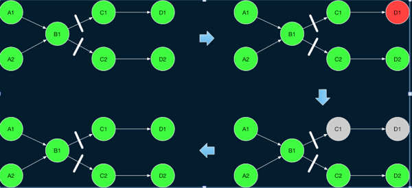
Figure 10. Region-based error recovery policy example.
If the error is caused by the downstream task itself, you can only restart the corresponding downstream region.
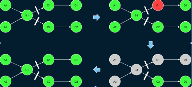
Figure 11. Region-based error recovery policy example.
If the error is caused by the upstream failure, restart the upstream and downstream regions at the same time. If the downstream output uses an indeterministic data partitioning method, restart all downstream regions of the upstream region at the same time to maintain data consistency.
In addition to task execution exceptions, another type is an exception on the Flink cluster master. Currently, Flink supports starting multiple masters as backups. These masters can be selected through ZK to ensure that only one master is running at a certain time. When the master of the active route fails, a backup master takes over the coordination. To ensure that the master can accurately maintain the job status, Flink currently uses the simplest implementation method, that is, to directly restart the entire job. In fact, this method can still be improved because the job itself may be running normally.
Flink is continuously iterated and updated in the runtime aspect. As currently envisaged, Flink may continue to be optimized and expanded in the following ways.

151 posts | 43 followers
FollowApache Flink Community China - December 25, 2019
Apache Flink Community China - September 16, 2020
Apache Flink Community China - September 16, 2020
Apache Flink Community - October 12, 2024
Apache Flink Community China - April 19, 2022
Apache Flink Community China - September 16, 2020

151 posts | 43 followers
Follow Realtime Compute for Apache Flink
Realtime Compute for Apache Flink offers a highly integrated platform for real-time data processing, which optimizes the computing of Apache Flink.
Learn More EasyDispatch for Field Service Management
Apply the latest Reinforcement Learning AI technology to your Field Service Management (FSM) to obtain real-time AI-informed decision support.
Learn More Message Queue for Apache Kafka
A fully-managed Apache Kafka service to help you quickly build data pipelines for your big data analytics.
Learn More Super App Solution for Telcos
Alibaba Cloud (in partnership with Whale Cloud) helps telcos build an all-in-one telecommunication and digital lifestyle platform based on DingTalk.
Learn MoreMore Posts by Apache Flink Community