By Yu Kai
Co-Author: Xie Shi (Alibaba Cloud Native Application Platform)
In recent years, the trend of enterprise infrastructure cloud-native has become popular. From the initial IaaS to the current microservice, customers have more demands for fine granularity and observability. Container network has been developing at a high speed to meet customers' requirements for higher performance and higher density. This brings high thresholds and challenges to customers' observability of cloud-native networks. In order to improve the observability of the cloud-native network and facilitate the readability of business links for customers and frontend and backend developers, ACK and AES jointly developed the observability series of ack net-exporter and cloud-native network data planes to help them understand the cloud-native network architecture system. It lowers the observability threshold of the cloud-native network and optimizes the experience of customer operation and maintenance and after-sales on difficult problems. It improves the stability of cloud-native network links.
The entire container network can be divided into Pod, Service, and Node CIDR blocks. If these three networks want to achieve interconnection and access control, what is the technical principle? What is the whole link? What are the restrictions? What is the difference between Flannel and Terway? What is the network performance in different modes? These require customers to choose according to their business scenarios before building containers. After building containers, the relevant architecture cannot be changed. Thus, customers need to have a full understanding of the characteristics of each architecture. For example, the following figure is a schematic diagram. The pod network realizes network communication and control between pods of the same ECS and access between different ECS Pods. The backend of pods accessing SVC may be on the same ECS or other ECS. Under different modes, the data link forwarding modes are different, and the performance from the service side is also different.
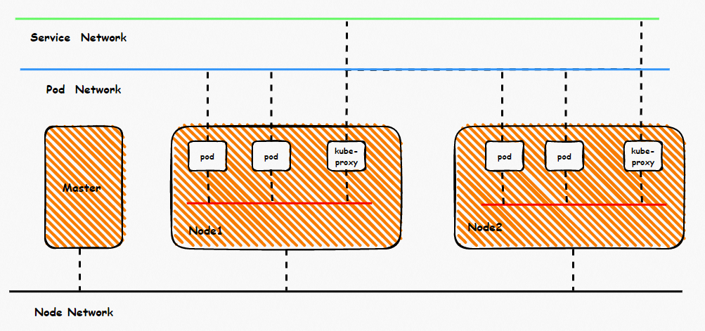
This article is the first part of the series. It introduces the forwarding links of data plane links in Kubernetes Flannel mode. First, by understanding the forwarding links of the data plane in different scenarios, it can find the reasons for the performance of customer access resulting in different scenarios and help customers further optimize the business architecture. On the other hand, by understanding the forwarding links in-depth, customer O&M and Alibaba Cloud developers can know which link points to deploy and observe manually to delimit the direction and cause of the problem.
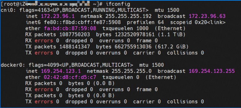
Under Flannel mode, an ECS instance only has one primary ENI and no other secondary network interface controller. Pods on the ECS instance and nodes communicate with external servers through the primary network interface controller. ACK Flannel creates a virtual cni0 on each node as a bridge between the pod network and the primary cni0 ECS.
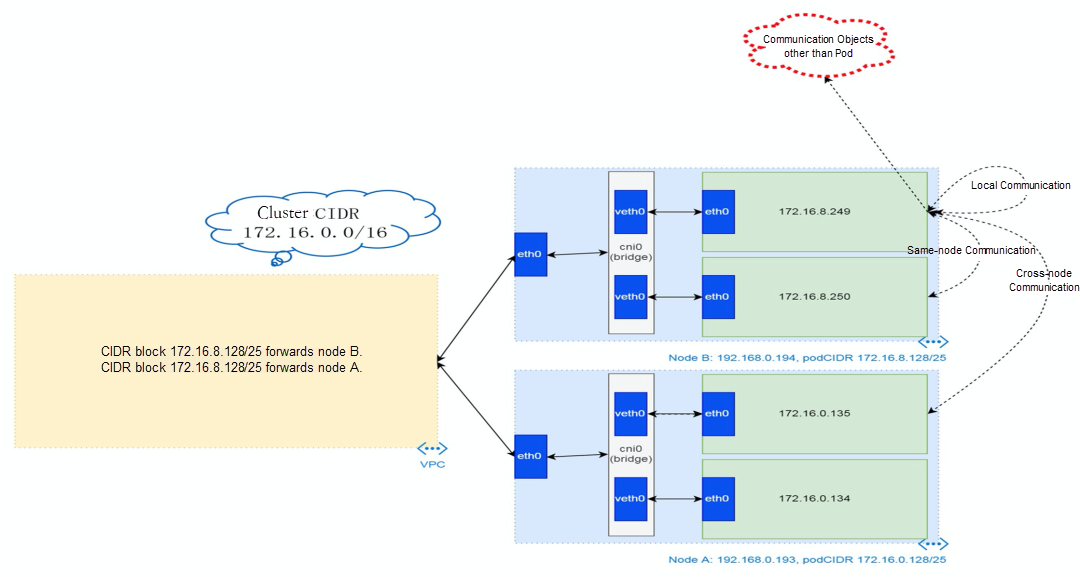
Each node of the cluster starts a flannel agent and pre-allocates a pod CIDR block to each node. This pod CIDR block is a subset of the pod CIDR block of the ACK cluster.

The network namespace of the container contains a virtual network interface controller of eth0 and a route with a next hop that points to the network interface controller. The network interface controller serves as an ingress and egress for data exchange between the container and the host kernel. The data link between the container and the host is exchanged through the veth pair. Now that we have found one of the veth pairs, how can we find the other veth?


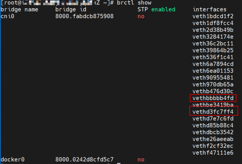
As shown in the figure, we can see eth0@if81 through p addr in the network namespace of the container, where '81' will help us find the other veth pair in the network namespace of the container in ECS OS. In ECS OS, we can find the vethd7e7c6fd virtual network interface controller through ip addr | grep 81:, which is the other veth pair on the ECS OS side.

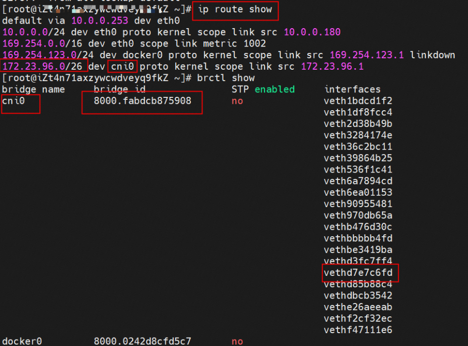
So far, connections between containers and OS data links have been established. How does data traffic in ECS OS determine which container to go to? From the OS Linux Routing, we can see that all traffic destined for the Pod CIDR block is forwarded to the virtual cni0. Then, cni0 points data link destined for different purposes to different vethxxx through the bridge mode. Up to this point, the network namespace of ECS OS and Pods has established a complete configuration of ingress and egress links.
Based on the characteristics of container networks, we can divide the network links in Flannel mode into two major SOP scenarios: Pod IP and SVC. We can subdivide them into ten different small SOP scenarios.
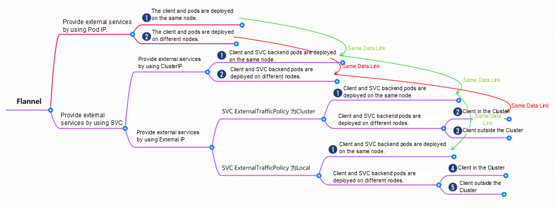
The data link of these ten scenarios can be summarized into the following five types of scenarios.
This scenario contains the following sub-scenarios. Data links can be summarized into one.

Two pods exist on the ap-southeast-1.10.0.0.180 node: centos-67756b6dc8-rmmxt IP address of 172.23.96.23 and nginx-7d6877d777-6jkfg of 172.23.96.24.
The centos-67756b6dc8-rmmxt IP address is 172.23.96.23. The PID of the container on the host is 503478, and the container network namespace has a default route pointing to container eth0.


This container eth0 corresponding to the veth pair in ECS OS is vethd7e7c6fd.


Through a similar method, the nginx-7d6877d777-6jkfg IP address 172.23.96.24 can be found, the PID of the container on the host is 2981608, and the corresponding veth pair of the container eth0 in ECS OS is vethd3fc7ff4.

In ECS OS, there is a route that points to the pod CIDR and the next hop is cni0 and the vethxxx bridge information of cni0 containing two containers.

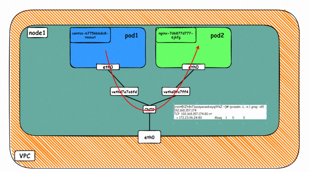
▲ Diagram of Data Link Forwarding
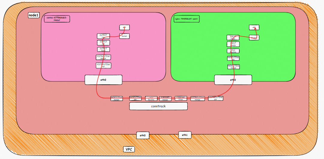
▲ Kernel Protocol Stack Diagram
This scenario contains the following sub-scenarios, data links can be summarized into one:

Two pods exist on the ap-southeast-1.10.0.0.180 node: centos-67756b6dc8-rmmxt IP address is 172.23.96.23 and nginx1-76c99b49df-7plsr IP address is 172.23.96.163.
The ExternalTrafficPlicy of Service nginx1 is Cluster.

The data exchange between the pod and ECS OS network space has been described in detail in 2.1 Scenario 1.
When the source data link accesses the clusterip 192.168.13.23 of svc, if the link reaches the OS of ECS, it will hit the IPVS rule and be resolved to one of the backend endpoints of svc (there is only one pod in this instance, so there is only one endpoint).

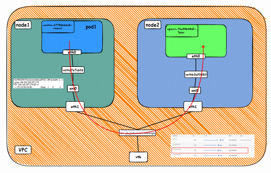
▲ Diagram of Data Link Forwarding
The VPC route table is automatically configured with the destination address pod CIDR block, and the next hop is the ECS custom route entry to which the POD CIDR block belongs. The rule is managed by ACK and configured by OpenAPI calling VPC. You do not need to manually configure or delete it.


▲ Kernel Protocol Stack Diagram
Node1:
Src is the source pod IP, dst is the ClusterIP of svc, and it is expected that one of the endpoints 172.23.96.163 of the svc sends messages to the source pod.

Node2:
The conntrack table on the ECS where the destination pod is located recordsthat the destination pod is accessed by the source pod, and the svc clusterip address is not recorded.

This scenario contains the following sub-scenarios, and the data link can be summarized into one:
1. The client and SVC backend pods are deployed on different nodes in the cluster when the SVC ExternalIP is used to provide external service, and ExternalTrafficPolicy is Local.

Two pods exist on the ap-southeast-1.10.0.0.180 node: centos-67756b6dc8-rmmxt IP address is 172.23.96.23, and nginx1-76c99b49df-7plsr IP address is 172.23.96.163.
Service nginx1 ExternalTrafficPolicy is Local.
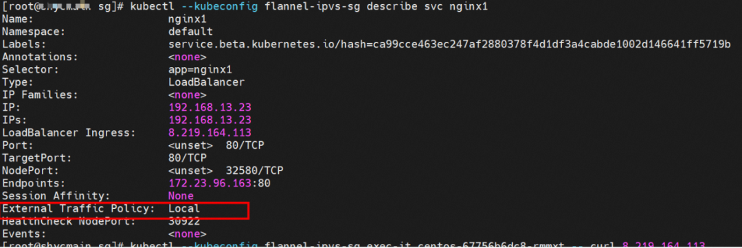
The data exchange between the pod and ECS OS network space has been described in detail in Scenario 1 in 2.1.
IPVS Rules of the ECS Where the Source Pod Resides
When the source data link accesses the externalip 8.219.164.113 of svc, if the link reaches the OS of ECS, it will hit the IPVS rule. However, EcternalIP does not have the relevant backend endpoint. After the link reaches the OS, it will hit the IPVS rule. But there is no backend pod, so a connection refused will appear.

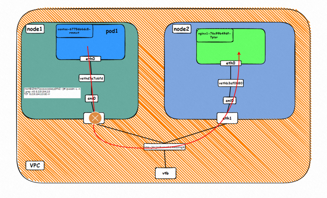
▲ Diagram of Data Link Forwarding

▲ Kernel Protocol Stack Diagram
This scenario includes the following sub-scenarios, and the data link can be summarized into one: A. When accessing SVC External IP and ExternalTrafficPolicy is Local, the client and server pods are deployed on different ECS instances, where the client is outside the cluster.

The Deployment is nginx1. The three pod nginx1-76c99b49df-4zsdj and the nginx1-76c99b49df-7plsr are deployed on the ap-southeast-1.10.0.1.206 ECS, and the last pod nginx1-76c99b49df-s6z79 is deployed on the other node ap-southeast-1.10.0.1.216.
The ExternalTrafficPlicy of Service nginx1 is Local.
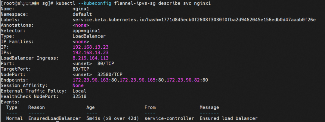
The data exchange between the pod and ECS OS network space has been described in detail in Scenario 1 in 2.1.
From the SLB console, you can see that there are only two ECS nodes ap-southeast-1.10.0.1.216 and ap-southeast-1.10.0.1.206 in the virtual server group at the backend of the SLB. Other nodes in the cluster (such as ap-southeast-1.10.0.0.180) are not added to the backend virtual server group of the SLB instance. The IP address of the virtual server group is the IP of ECS, and the nodeport is 32580 in the service.

Therefore, when the ExternalTrafficPolicy is in Local mode, only the ECS node where the Service backend pod is located will be added to the backend virtual server group of SLB and participate in the traffic forwarding of SLB. Other nodes in the cluster do not participate in the traffic forwarding of SLB.
From the two ECS instances in the SLB virtual server group, you can see that the IPVS forwarding rules for nodeip and nodeport are different. When the ExternalTrafficPolicy is set to Local mode, only the shorting pod on the node is added to the IPVS forwarding rule, and the backend pods on other nodes are not added. This ensures that the link forwarded by SLB is only forwarded to the pod on the node and not forwarded to other nodes.
node1: ap-southeast-1.10.0.1.206

node1: ap-southeast-1.10.0.1.216

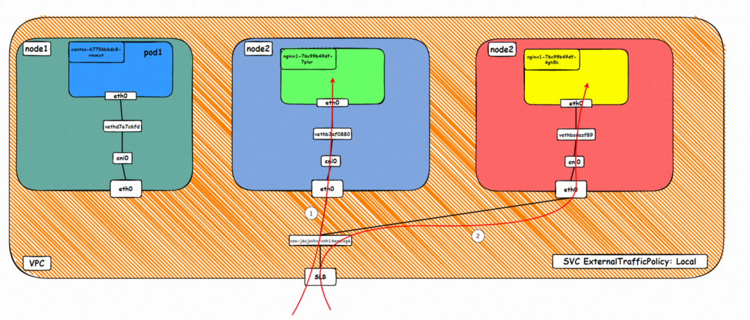
▲ Data Link Forwarding Diagram
This figure shows that only the ECS instance where the backend pod is deployed is added to the SLB backend server. The SVC externalIP (SLB IP) is accessed from outside the cluster. The data link is only forwarded to the ECS instance in the virtual server group and not to other nodes in the cluster.
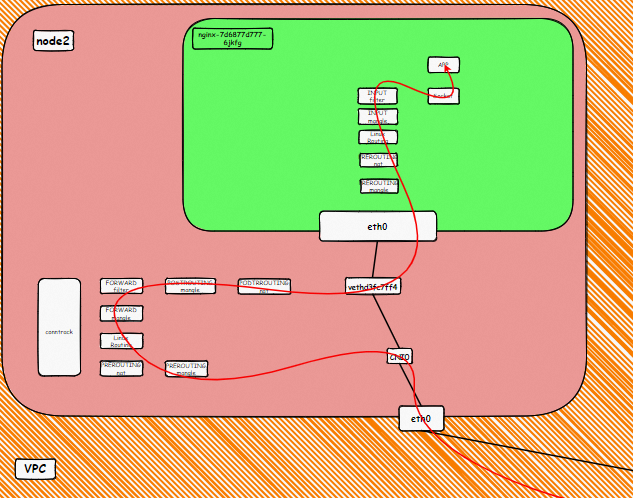
▲ Kernel Protocol Stack Diagram
Node:
Src is the cluster external client IP, dst is the node IP, and dport is the nodeport in SVC. The expectation is that pod 172.23.96.82 on the ECS will be packaged to the source.

This scenario contains the following sub-scenarios, and data links can be summarized into one.
1. When accessing SVCExternal IP, if the ExternalTrafficPolicy is Cluster, the client and server pods are deployed on different ECS instances. The client is outside the cluster.

The Deployment is nginx1. The three pods nginx1-76c99b49df-4zsdj and the nginx1-76c99b49df-7plsr are deployed on the ap-southeast-1.10.0.1.206 ECS. The last pod nginx1-76c99b49df-s6z79 is deployed on the other node ap-southeast-1.10.0.1.216.
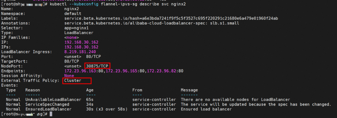
The ExternalTrafficPlicy of Service nginx2 is Cluster.
The data exchange between the pod and ECS OS network space has been described in detail in Scenario 1 in 2.1.
From the SLB console, all nodes ap-southeast-1.10.0.0.180, ap-southeast-1.10.0.1.216, and ap-southeast-1.10.0.1.206 in the cluster are added to the SLB virtual server group. The IP of the virtual server group is the ECS IP, and the nodeport is 30875 in the service.

Therefore, when ExternalTrafficPolicy is in the CLuster mode, all ECS nodes in the cluster are added to the SLB backend virtual server group to participate in the traffic forwarding of the SLB instance.
From the SLB virtual server group, you can see that the IPVS forwarding rules for nodeip and nodeport are consistent. When ExternalTrafficPolicy is under the Cluster mode, all service backend pods will be added to the IPVS forwarding rules of all nodes. Even if the node has a backend pod, the traffic will not necessarily be forwarded to the pod on the node but may be forwarded to the backend pods on other nodes.
node1: ap-southeast-1.10.0.1.206 (this node has a backend pod)

node1: ap-southeast-1.10.0.1.216 (this node has a backend pod)

node3: ap-southeast-1.10.0.0.180 (this node does not have a backend pod)

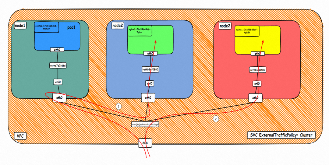
▲ Diagram of Data Link Forwarding
This figure shows that all ECS instances in the cluster are added to the SLB backend. Access the SVC's externalIP (SLB IP) from outside the cluster. Data traffic may be forwarded to other nodes.
The diagram of the kernel protocol stack has been described in detail in Scenario 1 in 2.4.
Link 1:
ap-southeast-1.10.0.0.180:
When the data link corresponds to link 1 in the diagram, you can see that the data link is transferred to the ap-southeast-1.10.0.0.180 node, and there is no backend pod of the service on this node. Through the conntrack information, you can see:
Src is the cluster external client IP, dst is the node IP, and dport is the nodeport in SVC. The expectation is that 172.23.96.163 will be packaged to 10.0.0.180. Through the preceding information, we can know that 172.23.96.163 is nginx1-76c99b49df-7plsr pod and is deployed in ap-southeast-1.10.0.1.206.

ap-southeast-1.10.0.1.206:
From the conntrack table of this node, it can be seen that src is node ap-southeast-1.10.0.0.180, dst is port 80 of 172.23.96.163, and the package is returned to node ap-southeast-1.10.0.0.180.

In summary, we can see that src has been changed many times, so the real client IP will be lost in the CLuster mode.
Link 2:
Src is the cluster external client IP, dst is the node IP, and dport is the nodeport in SVC. The expectation is that pod 172.23.96.82 on the ECS will be packaged to 172.23.96.65. This address is in the SLB cluster.

This article focuses on the data link forwarding paths of ACK in Flannel mode in different SOP scenarios. With the development of microservices and cloud-native, network scenarios have become complex. As a Kubernetes-native network model, Flannel can be divided into 10 SOP scenarios for different access environments. Through in-depth analysis, it can be summarized into five scenarios. The forwarding links, technical implementation principles, and cloud product configurations of these five scenarios are sorted out and summarized. These will provide preliminary guidance to deal with link jitter, optimal configuration, link principles, etc. under the Flannel architecture. Next, we will enter the Terway mode of CNI developed by Alibaba, which is currently the most used mode for online clusters.
Analysis of Alibaba Cloud Container Network Data Link (2): Terway EN

210 posts | 13 followers
FollowAlibaba Developer - June 19, 2020
AlibabaCloud_Network - September 14, 2018
Alibaba Clouder - December 19, 2019
Alibaba Container Service - May 19, 2021
Alibaba Cloud Native - June 7, 2023
Alibaba Clouder - September 1, 2021

210 posts | 13 followers
Follow ACK One
Provides a control plane to allow users to manage Kubernetes clusters that run based on different infrastructure resources
Learn More Container Registry
A secure image hosting platform providing containerized image lifecycle management
Learn More Container Service for Kubernetes
Alibaba Cloud Container Service for Kubernetes is a fully managed cloud container management service that supports native Kubernetes and integrates with other Alibaba Cloud products.
Learn More Cloud-Native Applications Management Solution
Accelerate and secure the development, deployment, and management of containerized applications cost-effectively.
Learn MoreMore Posts by Alibaba Cloud Native
Start building with 50+ products and up to 12 months usage for Elastic Compute Service
Get Started for Free Get Started for Free