Download the "Real Time is the Future - Apache Flink Best Practices in 2020" whitepaper to learn about Flink's development and evolution in the past year, as well as Alibaba's contributions to the Flink community.
By Zhang Jun (Apache Flink Contributor and R&D Director of the OPPO Big Data Platform)

This article was compiled from Zhang Jun's presentation at the Flink meetup held in Shenzhen on April 13, 2019.
Zhang Jun is an Apache Flink contributor and the R&D director of the OPPO big data platform.
This article covers the evolution of the OPPO real-time data warehouse, development of Flink SQL, cases of real-time data warehouse creation, and thoughts and prospects for the future.
As everyone knows, OPPO is a major smartphone manufacturer. However, you may not know how OPPO is connected to the Internet and big data fields. The following figure shows OPPO's businesses and data.
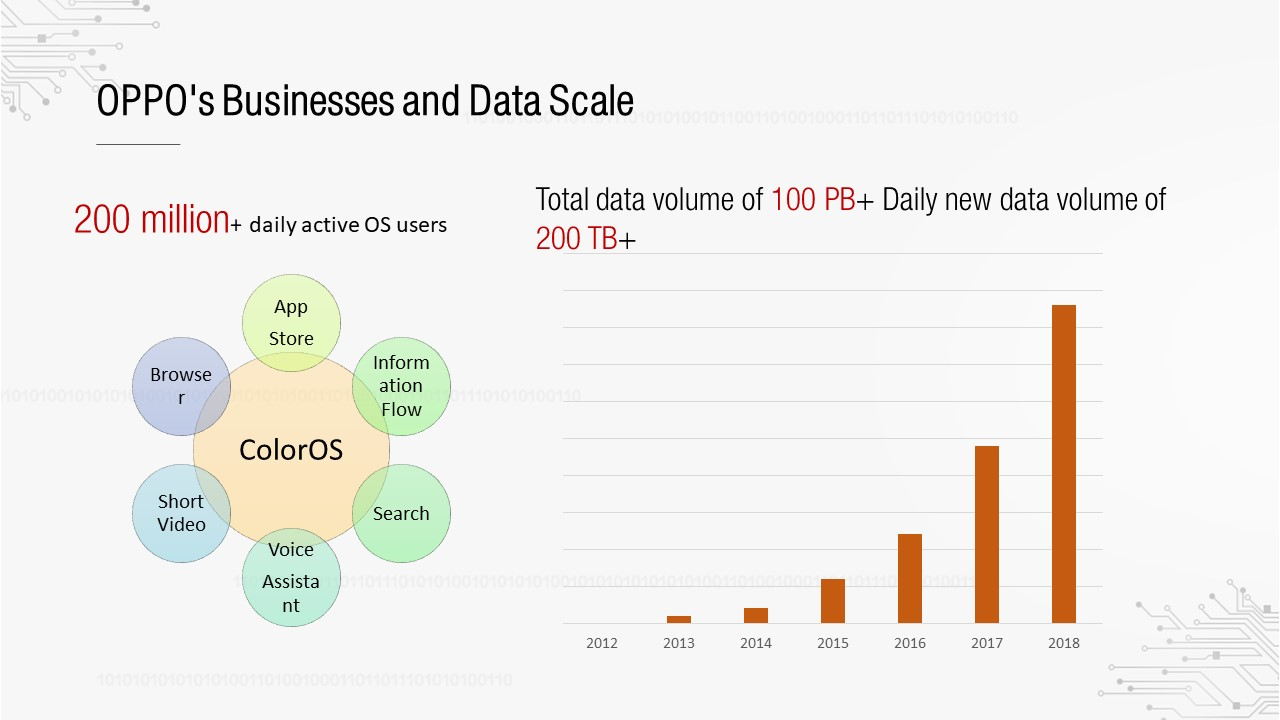
As a mobile phone manufacturer, OPPO customized its own ColorOS system based on the Android system. This system now has more than 200 million daily active users. OPPO has built many Internet applications for ColorOS, such as its app store, browser, and information flows. By operating these Internet applications, OPPO has accumulated a large amount of data. The right part of the preceding figure shows the overall data scale. Its data growth rate has doubled or tripled each year since 2012, and its total data amount now exceeds 100 PB now, with daily growth of more than 200 TB.
To support such a large data volume, OPPO has developed a complete set of data systems and services and formed its own data Mid-End system.
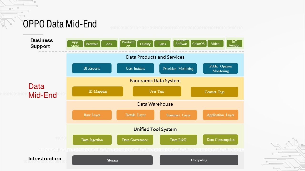
Mid-End is quite popular at the moment. How does OPPO view this concept? Mid-End is divided into four layers:
This is the entire OPPO Mid-End system, in which the data warehouse is the fundamental component.
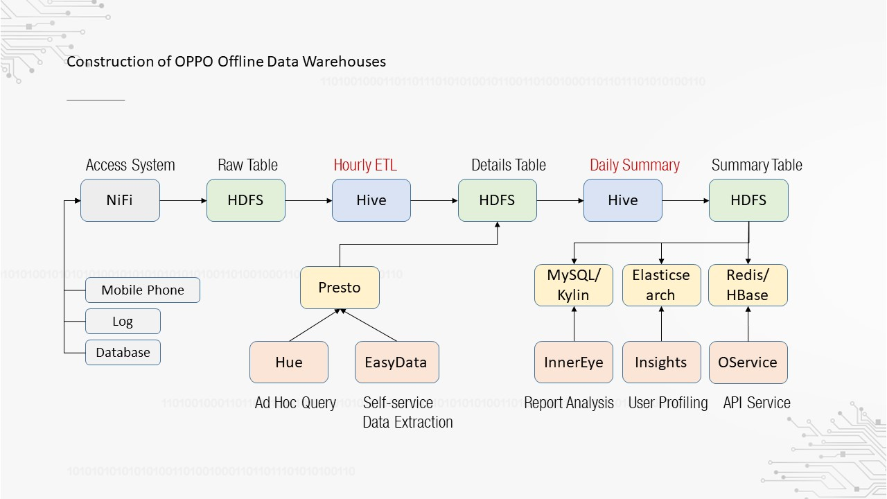
Over the past two or three years, we have focused on the construction of offline data warehouses. The preceding figure shows the entire construction process. First, data is obtained from mobile phones, log files, and databases. We have built a high-availability and high-throughput access system based on Apache NiFi and integrated data into HDFS, forming the raw layer. Then, the Hive-based hourly extract, transform, load (ETL) tasks and daily summary Hive tasks are executed to compute data and generate the details layer and summary layer respectively. Finally, internal data products developed by OPPO are deployed at the application layer, including report analysis, user profiling, and interface services. The details layer also supports Presto-based ad hoc queries and self-service data extraction.
With the gradual improvement of offline data warehouses, businesses have an increasing demand for real-time data warehouses.
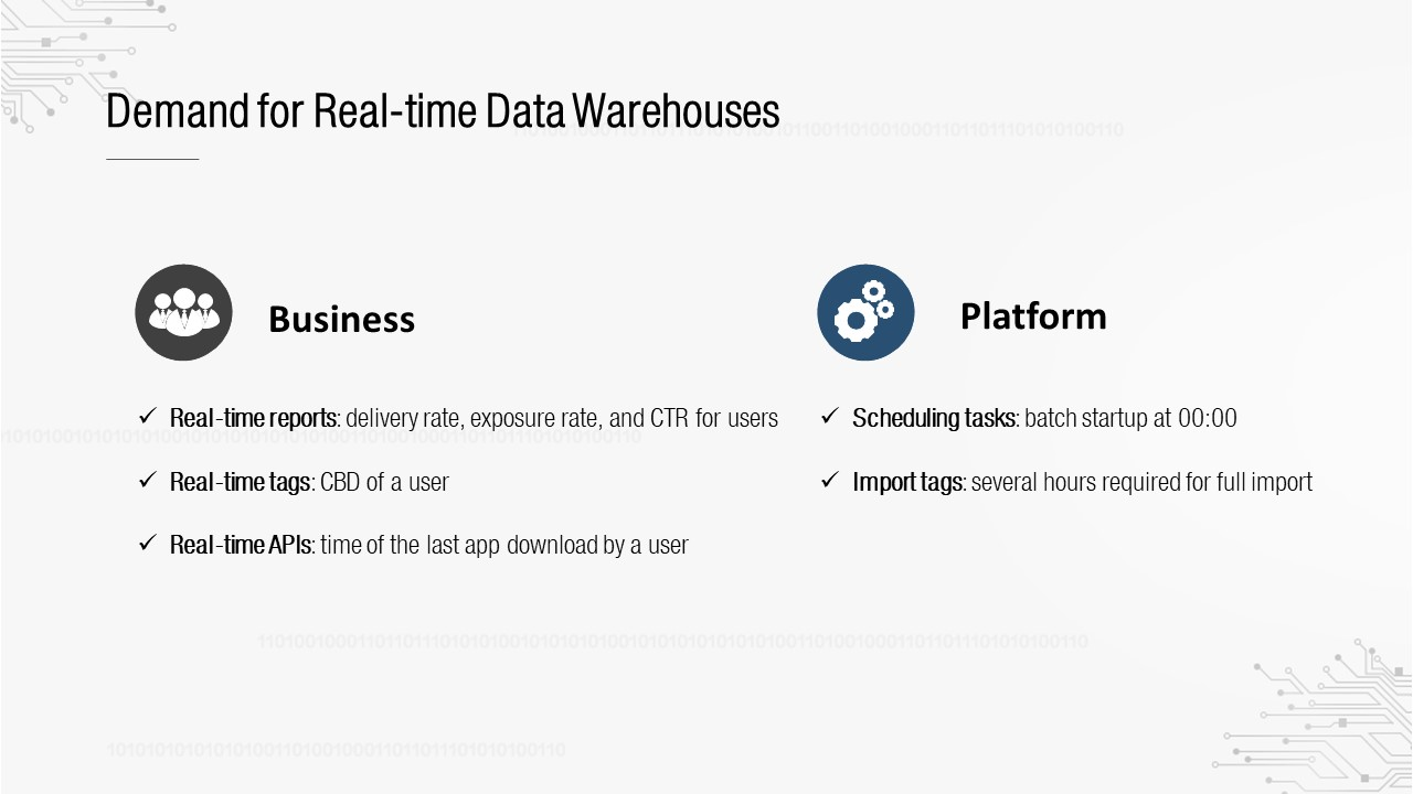
Real-time data warehouses are generally required for businesses and can also provide benefits to the platform. First, on the business side, there are real-time scenarios, such as reports, tags, and interfaces, as shown on the left in the preceding figure. Second, on the platform side, you can see three use cases: 1. A large number of OPPO batch tasks are started at 00:00 to process data in T+1 mode, which leads to a concentrated computing load and a heavy pressure on the cluster. 2. Tag import is also a T+1 batch task. Each full import takes a long time. 3. Data quality monitoring must be a T+1 task, so it will fail to promptly detect some data problems.
Since both the business side and the platform side require real-time data warehouses, how does OPPO build its own real-time data warehouses? This is what we will explore in the following section.
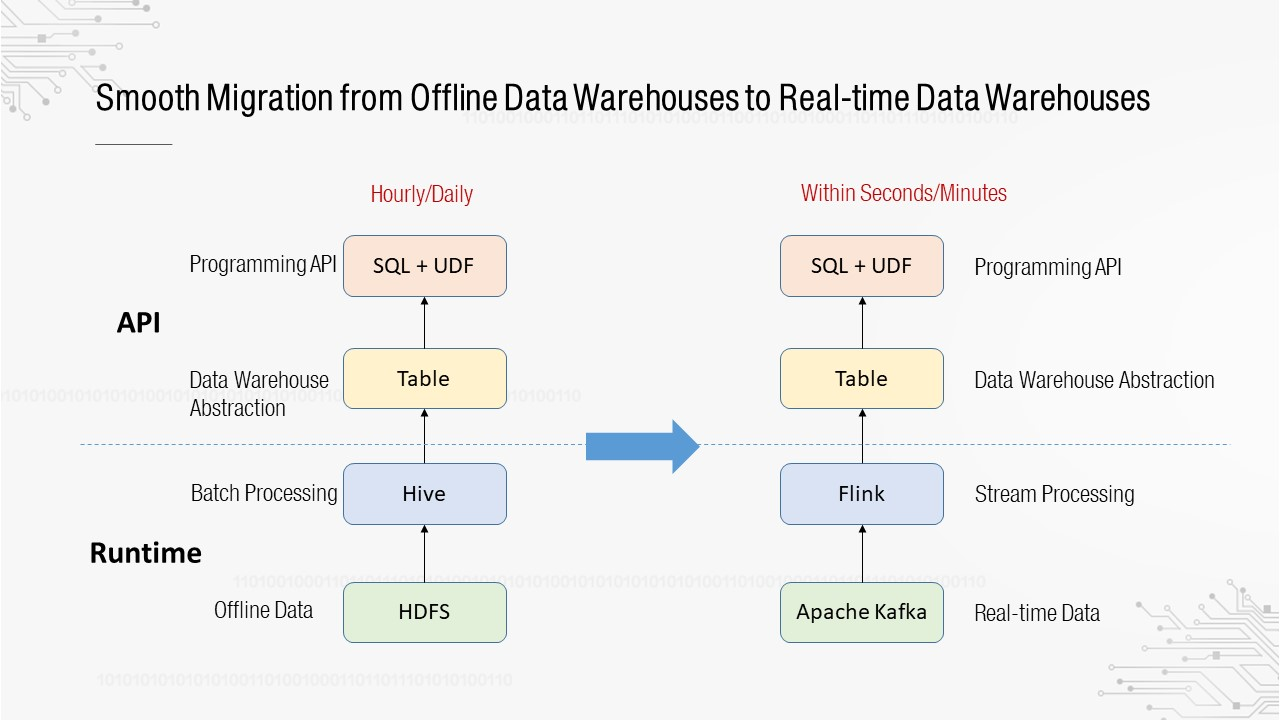
Both the platform and the system consist of two layers. The upper layer is an API layer, consisting of the user-oriented programming abstraction and APIs, and the lower layer is the runtime, a kernel-oriented execution engine. We want a smooth migration from offline data warehouses to real-time data warehouses. What does this entail? At the API layer, data warehouses are abstracted as tables, and the programming API is the SQL+UDF API. Users are familiar with this type of API from using offline data warehouses, so we want to continue to use it after migration to real-time data warehouses. At the runtime layer, the computing engine has been evolved from Hive to Flink, and the storage engine has been evolved from HDFS to Apache Kafka.
Following the preceding line of thinking, you only need to transform the offline data warehouse pipeline to get the real-time data warehouse pipeline.
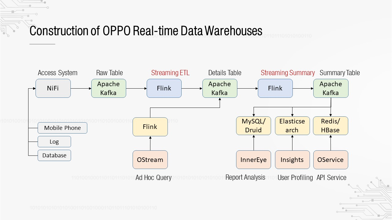
As shown in the preceding figure, the pipeline is similar to that of an offline data warehouse, except that Hive is replaced with Flink and HDFS is replaced with Apache Kafka. In the overall process, the basic model remains unchanged, which still consists of the cascading computing of the raw layer, details layer, summary layer, and application layer.
Therefore, the core issue here is how to construct the pipeline based on Flink. The next section describes the work we have done in this direction.
The following figure shows the basic structure of the Flink framework. The underlying layer is the runtime, which has four core advantages: low latency and high throughput, end-to-end exactly-once, fault-tolerant status management, and Windows time and event time support. Three layers of APIs are abstracted based on runtime, with the SQL API at the top layer.
A Flink SQL API has the following advantages: 1. It supports ANSI SQL standards. 2. It supports a wide range of data types and built-in functions, including common arithmetical operations and statistical aggregation. 3. It supports custom sources and sinks, based on which you can flexibly expand the upstream and downstream. 4. It supports batch and stream processing, allowing the same SQL statement to be run for offline and real-time data warehouses.
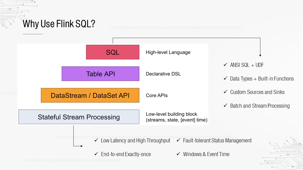
The following figure demonstrates how to use Flink SQL APIs for programming.
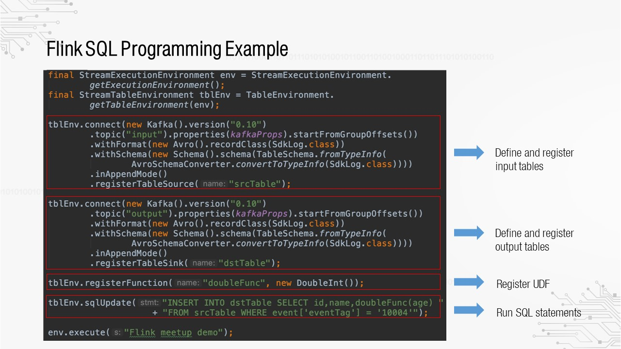
First, define and register the input and output tables. Two Apache Kafka tables are created, with the specified Apache Kafka version and topics. Second, register the user-defined function (UDF). Finally, execute the real SQL statement. As you can see, we need to perform a great deal of encoding before executing the SQL statement, so this is not the API we want to expose to users.
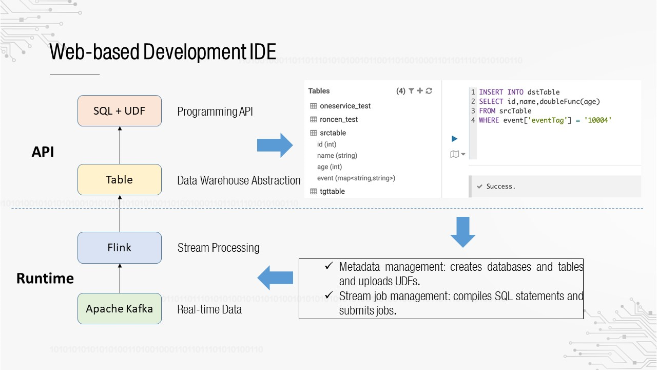
As mentioned above, data warehouses are abstracted as tables, and the programming API is the SQL+UDF API. The programming interface provided by the platform is similar to that in the preceding figure. Users who have used HUE for interactive queries should be familiar with it. The table list is displayed on the left and the SQL editor is displayed on the right. You can write SQL statements, and then submit them for execution. Flink SQL cannot implement such an interactive mode by default because it contains gaps. There are two main points we must consider: 1. Metadata management, that is, how to create databases and tables and how to upload UDFs for direct reference in SQL. 2. SQL job management, that is, how to compile SQL statements and how to submit jobs.
During our technical research, we discovered Uber's AthenaX framework, which was made open source in 2017.
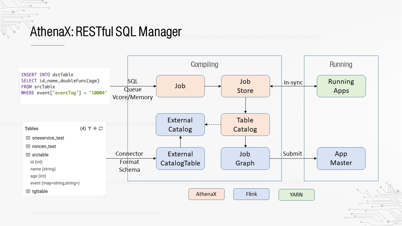
AthenaX can be used as a RESTful SQL manager, which implements SQL jobs and metadata management as follows:
Although AthenaX has defined the TableCatalog API, it does not provide a direct implementation.
The following describes how to connect Flink SQL to the existing metadata system.
First, we need to understand how databases and tables are registered in Flink SQL. The process involves three basic abstractions: TableDescriptor, TableFactory, and TableEnvironment.
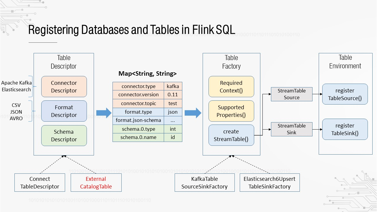
TableDescriptor is the description of a table, which consists of three sub descriptors: Connector, Format, and Schema.
Connector describes the data sources, such as Apache Kafka and Elasticsearch. Format describes the data format, such as CSV, JSON, and AVRO. Schema describes the name and type of each field. TableDescriptor provides two basic implementations: ConnectTableDescriptor, which describes internal tables (tables created by programming), and ExternalCatalogTable, which describes external tables.
Then a TableFactory is used to instantiate tables based on TableDescriptor. Each different descriptive information item is processed by a different TableFactory. This means we have to find a matching implementation for TableFactory in Flink. To ensure the scalability of the framework, Flink uses the Java SPI mechanism to load each declared TableFactory and traverses them to find the TableFactory that matches the TableDescriptor. Before being passed to a TableFactory, TableDescriptor is converted into a map, with all descriptive information expressed in key-value format. A TableFactory defines two matching methods: requiredContext() is used to check whether the values of certain keys are matched, for example, whether the value of the connector.type key is kafka. The second method, supported- Properties(), is used to check whether a key can be identified. If a key fails to be identified, its value cannot be matched.
After a correct TableFactory is matched, create a table and register it with TableEnvironment. Only successfully registered tables can be referenced in SQL statements.
Based on the process of registering databases and tables in Flink SQL, we can see the following: If a table created with external metadata can be converted into a table that can be recognized by a TableFactory, it can be seamlessly registered with TableEnvironment. Based on this idea, we have connected Flink SQL to the existing Metadata Center, as shown in the following figure.
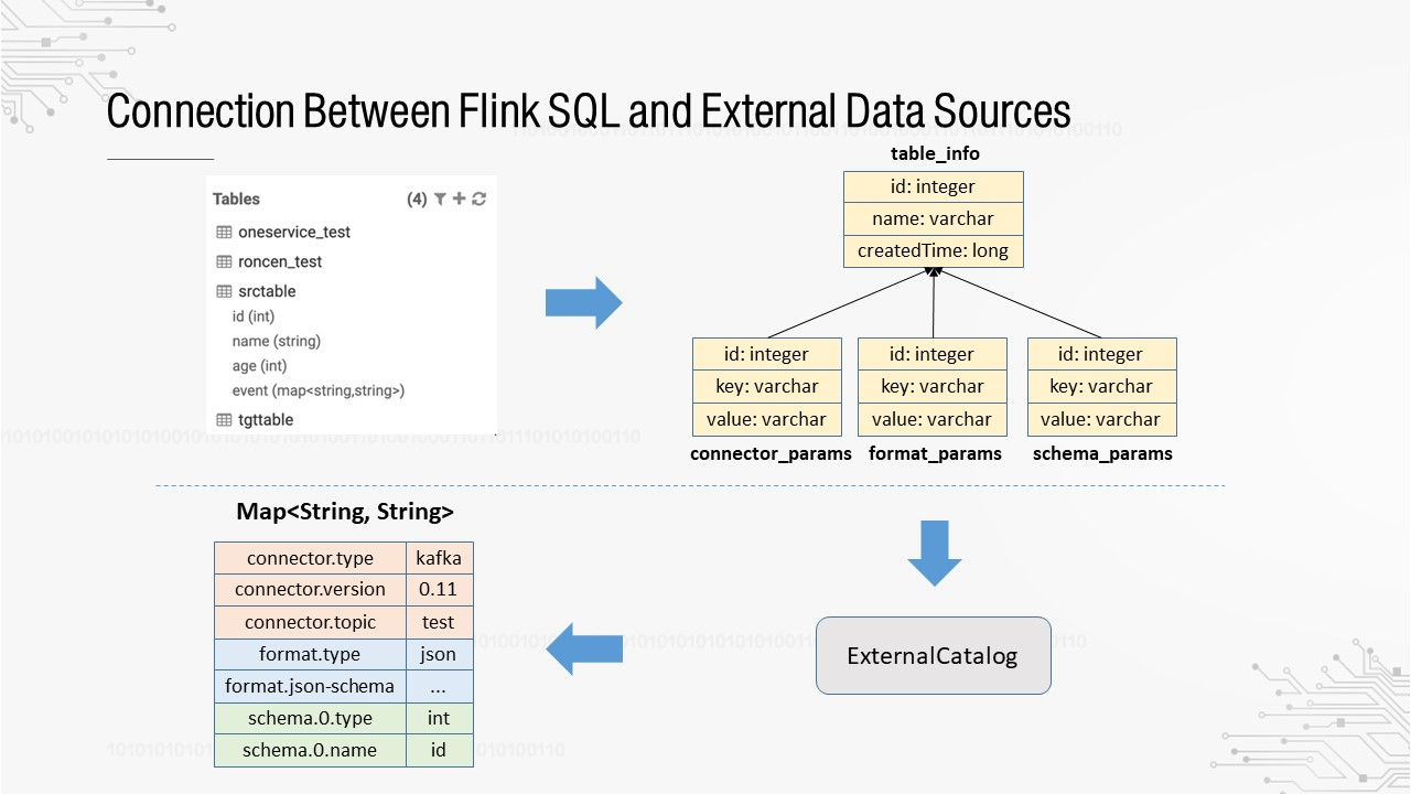
Metadata in all tables created in the Metadata Center is stored in the MySQL database. We use one table to record basic table information and three other tables to record the descriptive information after Connector, Format, and Schema are converted into the key-value format. Using the three tables, the three types of descriptive information can be updated separately.
The next step is to customize and implement ExternalCatalog, which can read the four MySQL tables and convert them to the map structure.
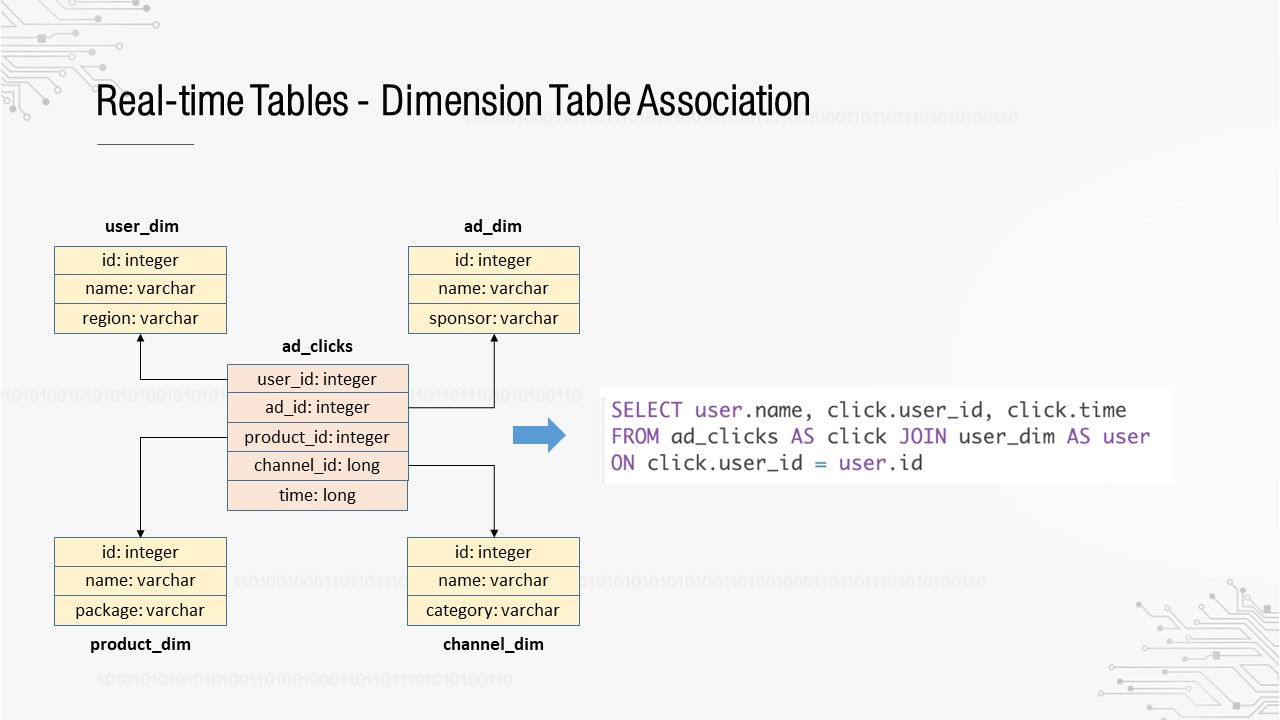
The platform has the ability to manage metadata and SQL jobs. However, some basic features are lacking, which must be provided before it is available to users. The star schema is required to build a data warehouse. For example, the fact table in the middle records the ad click stream, with dimension tables for users, ads, products, and channels nearby.
Assume that the click stream table needs to be associated with the user dimension table in Flink SQL. This can be implemented based on UDF or SQL conversion.
For UDF-based implementation, we need to rewrite the original SQL statement into a statement with UDF calls, for example, UserDimFunc. The right side in the preceding figure shows the code for implementation. UserDimFunc inherits
TableFunction, an abstraction of Flink SQL. It is a UDF type that can convert data of a row into one or more rows. To associate with dimension tables, we need to load full dimension table data from the MySQL database during UDF initialization and cache the data. In the subsequent processing of data in each row, TableFunction will call the eval() method to find the cache based on user_id in eval(). This accomplishes the association. In the preceding case, the dimension table contains a small amount of data. If a large amount of data is involved, full data loading and caching are not suitable.
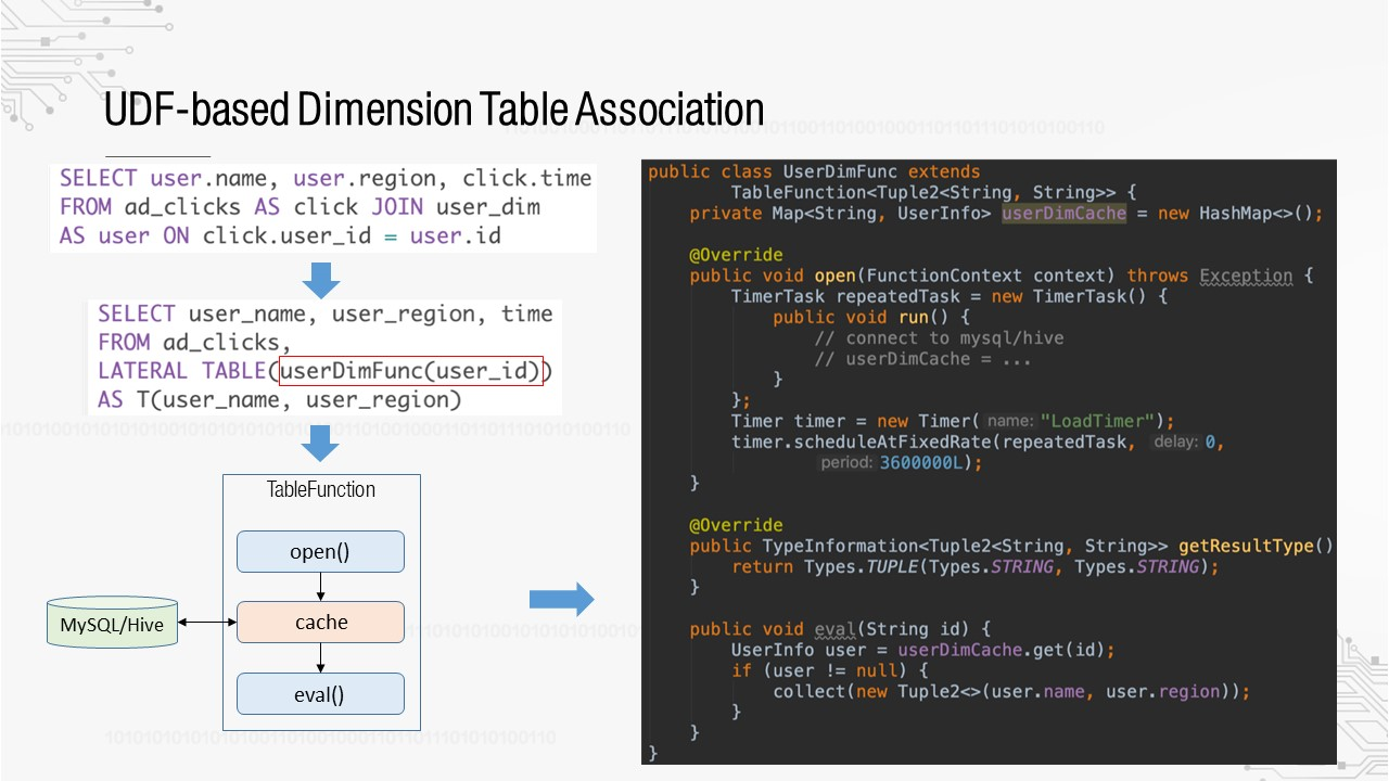
UDF-based implementation is not friendly to users or the platform. Users need to write strange SQL statements, such as LATERAL TABLE in the figure, while the platform needs to customize a specified UDF for each association scenario, which involves high maintenance costs. Is there a better way? Consider the implementation based on SQL conversion.
We need to solve the issues caused by UDF-based implementation so that users do not need to rewrite the original SQL statements and the platform does not need to develop many UDFs. We could add SQL statement parsing and rewriting before transferring an SQL statement to Flink for compilation to automatically associate dimension tables. This type of SQL conversion-based implementation has been shown to work through technical research and proof of concept (POC). The following explains the idea in detail.
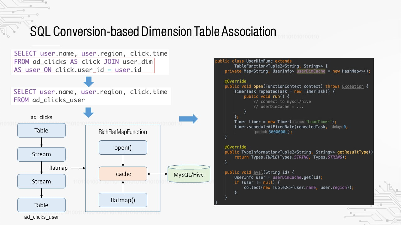
First, SQL statement parsing is added to identify whether a dimension table, such as user_dim in the preceding figure, is pre-defined in the SQL statement. Once a dimension table is identified, the SQL statement rewriting process is triggered to rewrite the join statement in the red box into a new table. So how do we get this table? In recent years, the concept of "stream-table duality" has been developed in the real-time computing field. This concept has been put into practice in Flink. That means conversion between streams and tables is implemented in Flink. We convert the table corresponding to ad_clicks to a stream, call flatmap to form another stream, and then convert it back to a table to get ad_clicks_user. How does flatmap implement the dimension table association?
In Flink, the flatmap operation for streams executes RichFlatmapFunction. The flatmap() method is called to convert the data of each new row. We can customize a RichFlatmapFunction to load, cache, query, and associate dimension table data. This has a function similar to that of TableFunction in UDF-based implementations.
Since the implementation logic of RichFlatmapFunciton is similar to that of TableFunction, why is it more useful than the UDF-based approach? The core of this method is an additional layer of SQL statement parsing, which can obtain the dimension table information, such as the dimension table name, associated fields, and select field, encapsulate the information into JoinContext, and transfer it to RichFlatmapFunciton. This makes the expressions more recognizable.
The following are several typical cases, which are implemented by using Flink SQL on the platform.
This is a typical real-time ETL process of splitting large tables into small tables for each business.
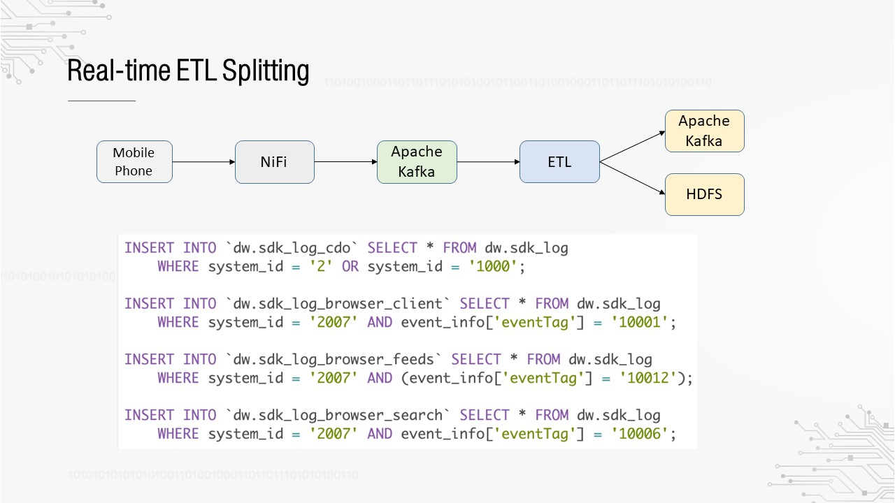
OPPO's largest data source is mobile phone tracking. All data obtained from mobile apps is reported through several unified channels because it is impossible to upgrade the client and add new channels for every new tracking point. For example, all app tracking points report data to the sdk_log channel, resulting in a huge raw layer table (dozens of TB per day) for this channel. In fact, each business only cares about its own data, which requires ETL splitting at the raw layer.
The SQL logic is simple. It only filters data based on certain business fields and inserts it into different business tables. This logic merges multiple rows of SQL statements into one SQL statement and submits it to Flink for execution. Since there are four SQL statements, will the same data be read four times? In fact, some optimizations are made during SQL statement compilation in Flink so that data will be read only once because it is destined for the same Apache Kafka topic.
In addition, Flink SQL is used for ETL splitting of offline and real-time data warehouses, which are stored in HDFS and Apache Kafka respectively. Flink can write data into HDFS sinks, such as RollingFileSink.
The following case describes how to calculate the click-through rate (CTR) of information flows. The number of exposures is divided by the number of clicks to obtain the CTR, which is then imported to the MySQL database. Then, the result is visualized in the internal report system. The SQL statement uses tumbling windows and subqueries.
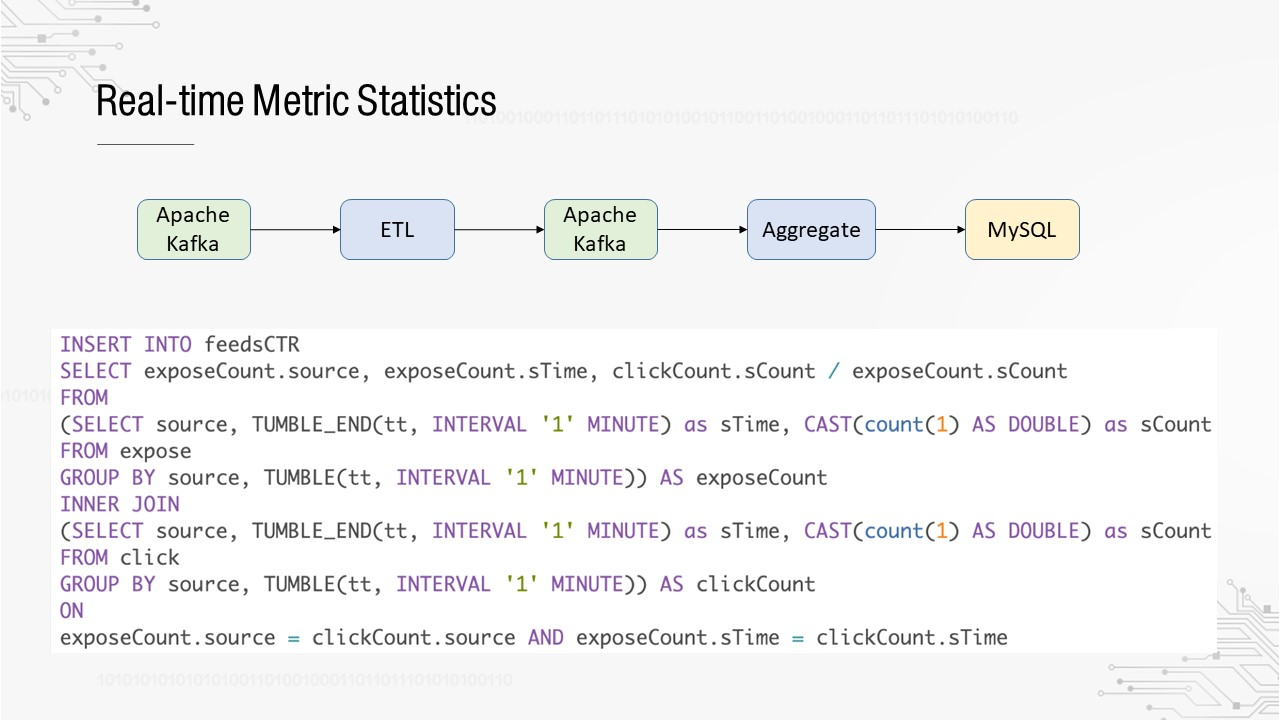
The following case describes how to import tags in real time. The mobile phone detects the longitude and latitude of the user in real time, converts them into a specific POI, and then imports it to Elasticsearch. Finally, the tag system performs user targeting.
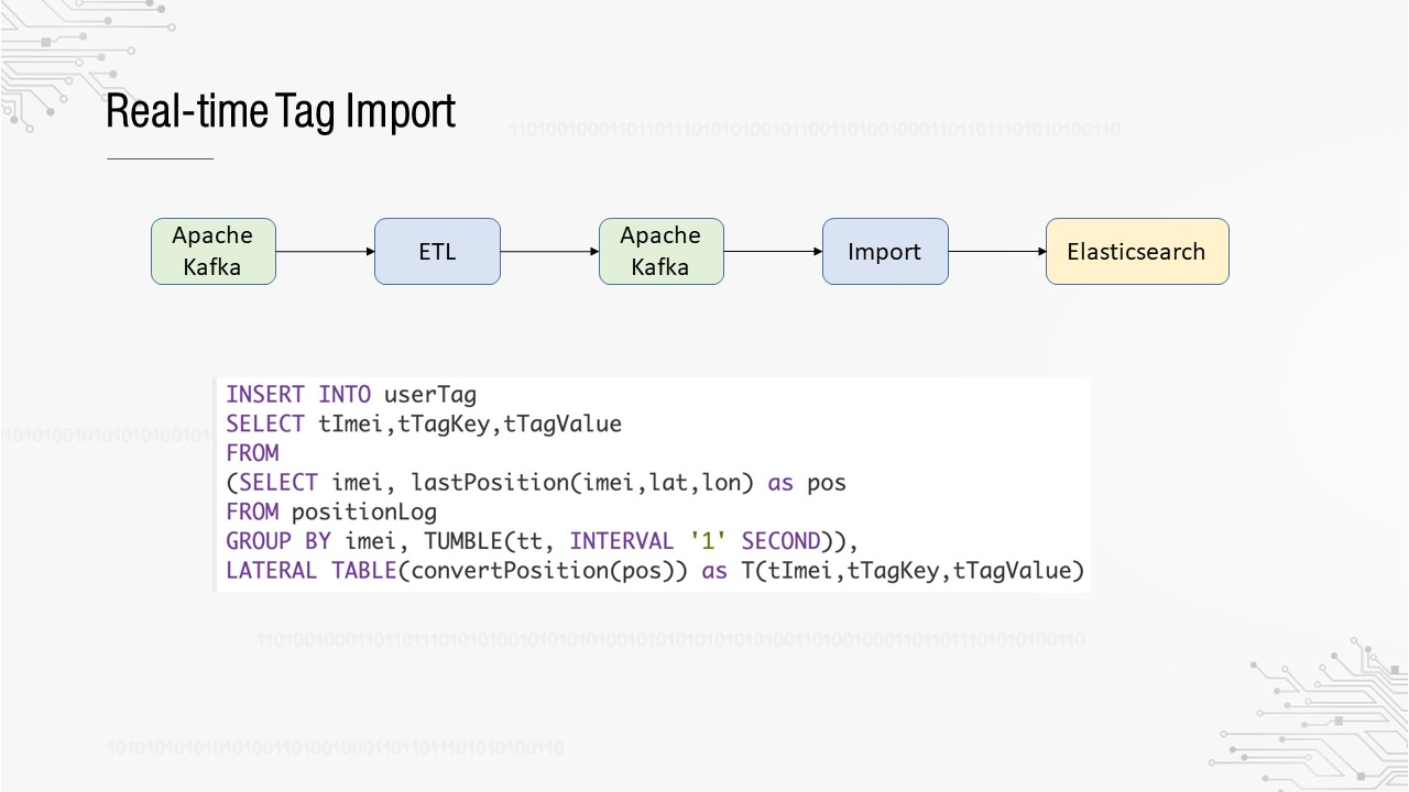
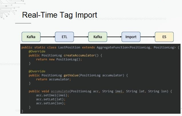
This SQL statement uses AggregateFunction. We only care about the latest longitude and latitude reported by the user in the 5-minute window. AggregateFunction is a UDF type, which is used for aggregation metric statistics, such as sum or average. In this case, we only care about the latest longitude and latitude, so we only need to replace the old data each time.
This section shares some of our thoughts and plans for future work.
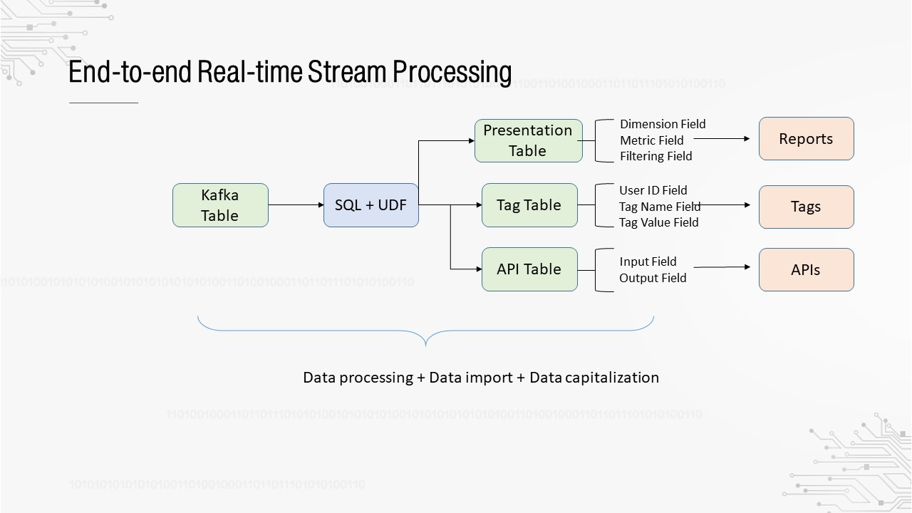
What is end-to-end? One end is the collected raw data, and the other end is the presentation and application of data in the form of reports, tags, and APIs. The two ends are connected by real-time streams. Currently, we implement real-time stream processing based on SQL statements. Both the source and target tables are Apache Kafka tables. They are imported to Druid, Elasticsearch, or HBase through Apache Kafka. This design aims to improve the stability and availability of the overall process. Apache Kafka, as the buffer of downstream systems, can prevent downstream system exceptions from affecting real-time stream computing. It is easier to keep one system stable than to keep multiple systems stable. For real-time streams from Apache Kafka to Apache Kafka, the mature exactly-once semantics ensures consistency.
The preceding end-to-end process is completed in three separate steps that may be performed by different roles. Data must be processed by data developers, imported by engine developers, and capitalized by product developers.
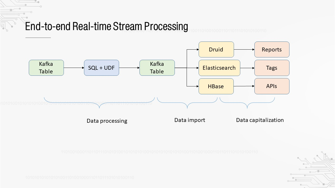
Can the platform automate the end-to-end process by submitting the SQL statement only once for data processing, import, and capitalization? In this way, what you see in data development is not an Apache Kafka table, but a scenario-oriented presentation table, tag table, or API table. For example, when creating a presentation table, you only need to specify fields such as the dimensions and metrics. The platform automatically imports the real-time stream result from Apache Kafka to Druid, and then automatically imports the Druid data source in the report system. It can even automatically generate a report template.
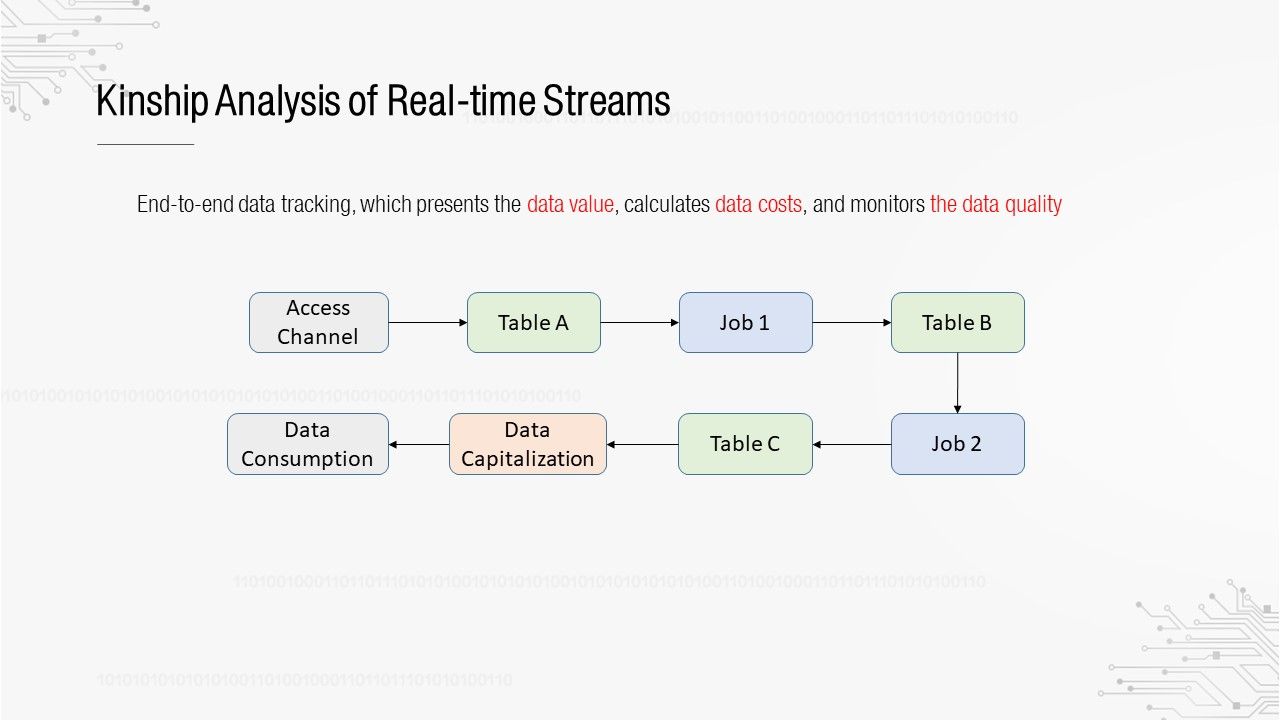
You may understand the importance of kinship analysis if you have used offline data warehouses. It assumes an indispensable role in data governance. This is also true for real-time data warehouses. We want to build an end-to-end kinship relationship, which contains the access channel of the collection system, intermediate real-time tables and jobs, and then the products that consume data. Based on the analysis of the kinship relationship, we can evaluate the application value of the data and calculate the computing costs.
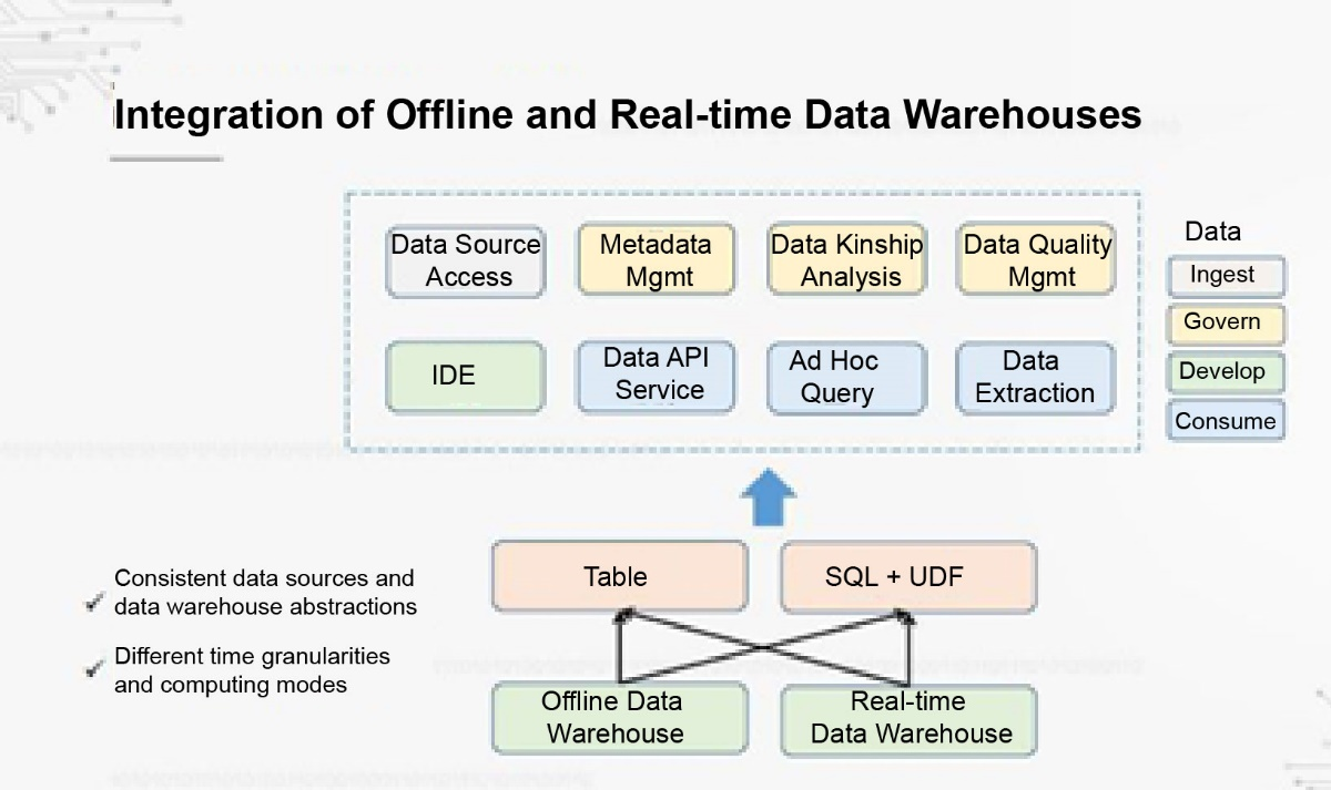
Finally, we are looking into the integration of offline and real-time data warehouses. In the short term, real-time data warehouses cannot replace offline data warehouses, so they will coexist. How can we adapt our tools and systems for offline data warehouses to real-time data warehouses and manage offline and real-time data warehouses together? Theoretically, their data sources are the same, and their upper-layer abstractions are tables and SQL statements. However, they also have differences, such as their time granularities and computing modes. We are exploring ways to transform data tools and products to achieve complete integration.
Netflix: Evolving Keystone to an Open Collaborative Real-time ETL Platform
Architecture Evolution and Application Scenarios of Real-time Warehouses in the Cainiao Supply Chain

150 posts | 43 followers
FollowApache Flink Community China - September 27, 2020
Alibaba EMR - January 10, 2023
Apache Flink Community China - November 5, 2020
Alibaba Clouder - December 2, 2020
Apache Flink Community China - September 27, 2020
Apache Flink Community China - January 11, 2021

150 posts | 43 followers
Follow Realtime Compute for Apache Flink
Realtime Compute for Apache Flink offers a highly integrated platform for real-time data processing, which optimizes the computing of Apache Flink.
Learn More Big Data Consulting for Data Technology Solution
Alibaba Cloud provides big data consulting services to help enterprises leverage advanced data technology.
Learn More MaxCompute
Conduct large-scale data warehousing with MaxCompute
Learn More Big Data Consulting Services for Retail Solution
Alibaba Cloud experts provide retailers with a lightweight and customized big data consulting service to help you assess your big data maturity and plan your big data journey.
Learn MoreMore Posts by Apache Flink Community