By Zehuan Shi
The Istio Ambient Mesh is a new architecture developed by the Istio community that separates the capabilities of Sidecars into Ztunnel and Waypoint. It also implements its own traffic rules using iptables and policy-based routing. While some articles have analyzed the implementation to some extent, there are still many details that have not been covered. The purpose of this article is to provide a detailed explanation of the Istio Ambient Mesh traffic path and present the details as clearly as possible, helping readers understand the critical parts of the Istio Ambient Mesh. It is assumed that readers have basic knowledge of the TCP/IP protocol, as well as operating system network knowledge including iptables and routing. Due to space limitations, this article will not provide a detailed introduction to these basic concepts. If readers are interested, it is recommended to refer to relevant materials for a more in-depth understanding.
Let's use a simple scenario to illustrate the Ambient Mesh traffic path: In a sleep pod running on Node A, an HTTP request is initiated through curl to a service named httpbin in the cluster. There is an httpbin pod on Node B under the service. Since the service (Cluster IP) is only a virtual IP in Kubernetes and not a real network device address, in this scenario, the request is directly sent to the httpbin application pod. The network path in this scenario would look like the figure below:
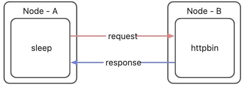
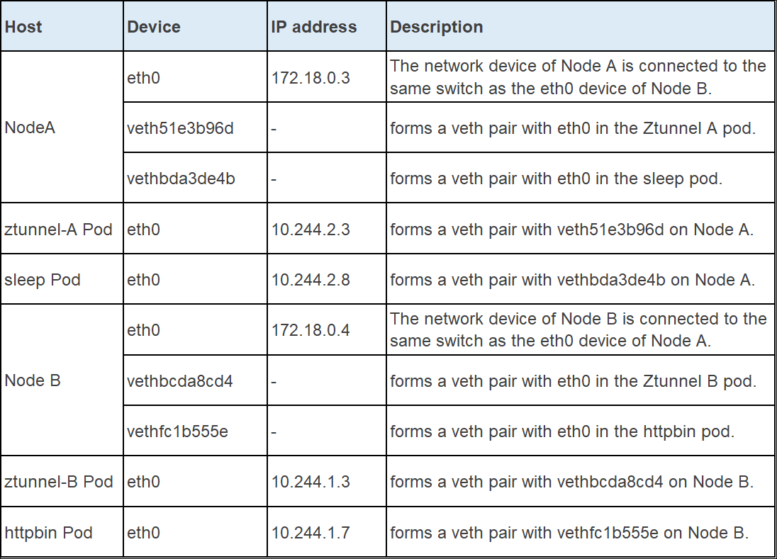
However, under the influence of Ambient Mesh traffic rules, packets sent from the sleep pod need to go through a series of iptables and policy-based routing and be forwarded to Ztunnel or Waypoint before reaching the httpbin application on the opposite end. To facilitate the description in the following pages, let's introduce all the participants in this process. It is not necessary to remember the IP addresses and names of these devices. They are listed here for reference purposes only.
Although the request path from sleep to httpbin seems simple, under the Ambient Mesh architecture, Ztunnel takes control of all incoming and outgoing connections. IP packets sent from the sleep pod will be redirected to Ztunnel's port 15001 and encrypted before being sent. Therefore, the connections initiated by the curl application in the sleep pod are actually connected to Ztunnel's protocol stack in the Ztunnel pod. Similarly, the connections received by the httpbin pod are actually from the Ztunnel running on the node where it is located. This means that there are actually three established TCP connections:
• sleep -> NodeA ztunnel
• NodeA ztunnel -> NodeB ztunnel
• NodeB ztunnel -> httpbin
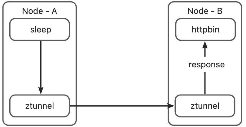
Ambient Mesh is designed as a Layer 4 transparent architecture. Although the intermediate proxy is forwarded by Ztunnel or Waypoint proxy, neither the curl application in the sleep pod nor the httpbin application in the httpbin pod can detect the presence of the intermediate proxy. In order to achieve this goal, data packets cannot be directly forwarded through DNAT and SNAT in many links, as these actions would modify the source and destination information of the data packets. The rules of the Ambient Mesh are designed to implement transparent transmission paths on both ends. To explain each part in detail, let's further refine the diagram:
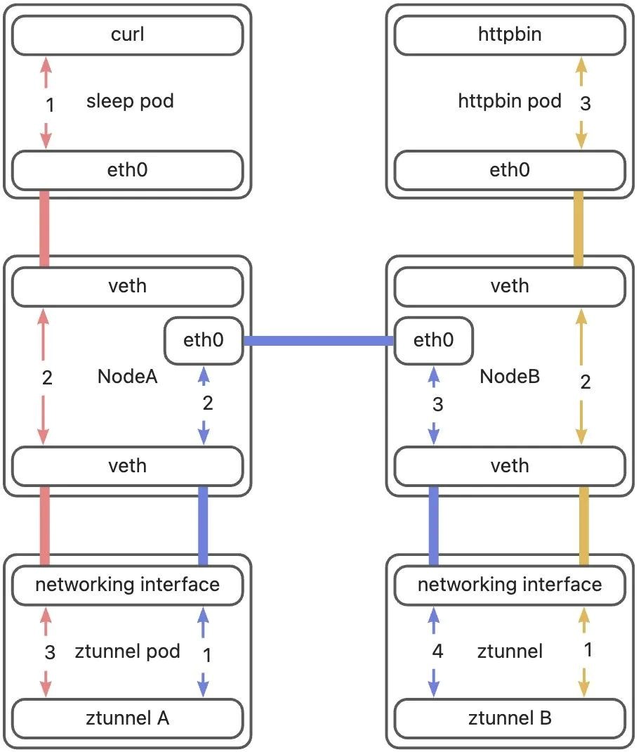
Let's interpret this diagram. I divided the entire path into three parts. The first part is from curl to Ztunnel A, indicated by red lines. The second part is from Ztunnel A to Ztunnel B, indicated by blue lines. The third part is from Ztunnel B to httpbin, indicated by yellow lines. Additionally, there are two types of lines. A line with no arrows on both ends indicates a direct connection, meaning that data packets enter from one end and exit from the other end. Although the connection mode of the eth0 devices between the two hosts differs from the connection mode of pods and hosts, this is not the focus of this article. We consider it as a direct connection as well. This article will focus on explaining the lines with arrows, analyzing the three parts of the path mentioned earlier, and clarifying how a data packet is forwarded at different parts of the path.
When we use curl to send a request, curl establishes a connection to the httpbin service. After DNS resolution, the connection target is the Cluster IP of the httpbin service, not the pod. In a Kubernetes cluster, the packets destined for the Cluster IP are converted into Pod IP through a series of iptables rules, and then sent through the host. However, in Ambient Mesh, the packets need to be encrypted by Ztunnel before being sent. In this section, we will first examine how packets are routed to the Ztunnel process in the Ztunnel pod.
The sleep pod has only one network device, eth0, which is one end of the pod's veth pair in the pod network namespace. The other end is the vethbda3de4b device in the host network namespace. All network communications between the pod and the outside world are transmitted through this channel. In Sidecar mode, the pod network namespace contains a series of iptables rules to redirect traffic to Sidecars. However, in Ambient mode, since Sidecars are no longer injected into pods, the pod network namespace does not have any iptables rules. Therefore, the traffic path at this stage is the same as that of a standard Kubernetes pod. The data packets sent from the pod's network protocol stack are sent through the pod's only network device, eth0. The packets then reach the host's network namespace from the host side's veth device.

After the data packets reach the host, they need to be redirected to Ztunnel. However, the first data packet and subsequent data packets on this path (TCP handshake data packet) are forwarded to Ztunnel in different ways. Let's start with the first data packet. The curl connection initiated by the sleep pod is to the httpbin service. After DNS resolution, the actual connection target is the Cluster IP of the httpbin service. Therefore, the source and destination addresses of the Layer 3 packets sent by the sleep pod's protocol stack are as follows:

Kubernetes configures iptables rules for service routing to transform the service address into a specific endpoint address through DNAT. In order to bypass this logic and redirect packets to Ztunnel, Ambient Mesh CNI adds some iptables rules and routing rules for the host before the Kubernetes rules. After the packet arrives at the host from the veth in the sleep pod, the PREROUTING chain is executed. Let's take a look at the contents of the PREROUTING chain.
=== PREROUTING ===
    --- raw ---
    --- mangle ---
        -A PREROUTING -j ztunnel-PREROUTING
    --- nat ---
        -A PREROUTING -j ztunnel-PREROUTING
        -A PREROUTING -m comment --comment "kubernetes service portals" -j KUBE-SERVICES
        -A PREROUTING -d 172.18.0.1/32 -j DOCKER_OUTPUT
It can be seen that Istio Ambient Mesh has added rules in the mangle table and nat table to forcibly redirect the packets to the ztunnel-PREROUTING chain for processing. Since the jump to the ztunnel-PREROUTING chain is unconditional, the data packets sent by a pod that not belongs to Ambient Mesh will also jump to this chain for processing. In order to avoid redirecting the traffic of a pod outside the mesh to Ztunnel by mistake, when the pod is started, Ambient Mesh CNI will determine the pod. If the result is to enable Ambient, the IP address of this pod is added to the ipset named ztunnel-pods-ips in the host network namespace. In the scenario in this article, the sleep pod will be added to an ipset named ztunnel-pods-ips on Node A, so packets from the sleep pod will hit the following rules in the ztunnel-PREROUTING chain (The rules omit content that is irrelevant to the current stage):
=== ztunnel-PREROUTING ===
    --- raw ---
    --- mangle ---
        ......
        -A ztunnel-PREROUTING -p tcp -m set --match-set ztunnel-pods-ips src -j MARK --set-xmark 0x100/0x100
    --- nat ---
        -A ztunnel-PREROUTING -m mark --mark 0x100/0x100 -j ACCEPT
    --- filter ---
In the mangle table execution phase, because the source address (sleep Pod address) of the packet is within the ztunnel-pods-ips, this rule is matched successfully, and the packet will be marked with 0 x 100. Such a packet will be directly accepted in the subsequent nat table execution phase, and the packet does not need to be processed by the iptables rules of Kubernetes. So far, the rules only mark the data packet, and the destination address of the data packet has not changed. To change the routing of the data packet, the routing table is needed. After PREROUTING ends, the data packet will enter the routing phase. Since the data packet is marked with 0 x 100, the following rules will be hit in the policy-based routing phase (irrelevant rules are omitted):
......
101:    from all fwmark 0x100/0x100 lookup 101
......
After this policy-based routing rule is hit, routing table 101 will be used for the packet. Let's look at the contents of routing table 101:
default via 192.168.127.2 dev istioout
10.244.2.3 dev veth51e3b96d scope link
Because the destination address of the packet is the Cluster IP of the httpbin service, in the demo environment used in this article, the Cluster IP of the httpbin service is 10.96.0.105, so it will hit the default rule in this routing table. The rule means that send the packet to the gateway 192.168.127.2 through the istioout device. The istioout device is a bridge device. The other end of the istioout device is the pistioout device in the Ztunnel pod, and its address is 192.168.127.2. After this routing rule is applied, the data packet will leave the host through the istioout device and then reach the Ztunnel pod network namespace from the pistioout device.

After the data packet reaches the Ztunnel pod network namespace through pistioout, the data packet will be discarded by the protocol stack of the Ztunnel pod if there is no intervention because the destination address of the data packet does not belong to any network device in the Ztunnel pod. The outbound proxy of the Ztunnel process listens on port 15001. In order to send the packet to this port, some iptables rules and routing rules are also set in the Ztunnel pod. After the packet reaches the Ztunnel pod network namespace, the following rule is hit:
=== PREROUTING ===
    --- raw ---
    --- mangle ---
        ......
        -A PREROUTING -i pistioout -p tcp -j TPROXY --on-port 15001 --on-ip 127.0.0.1 --tproxy-mark 0x400/0xfff
        ......
    --- nat ---
    --- filter ---
This rule resets the destination address of the data packet entering from the pistioout device to port 15001 whose IP address is 127.0.0.1, and marks the data packet with 0x400. It should be noted that although the destination address is redirected here, tproxy will retain the original destination address of the data packet, and the application can obtain the original destination address of the data packet through the SO_ORIGINAL_DST option of getsockopt. After the iptables rules are executed, the policy-based routing will be executed, and the packet will hit the following policy-based routing rules:
20000: from all fwmark 0x400/0xfff lookup 100This policy-based routing specifies that the routing table 100 is used for routing. Let's look at the contents of the routing table 100:
local default dev lo scope hostThe routing table 100 has only one rule, that is, the data packet is sent to the native protocol stack through the I/O device. At this point, the data packet enters the native protocol stack of the Ztunnel pod. Since the data packet is redirected to 127.0.0.1:15001 in iptables, the data packet finally reaches port 15001 listened to by the Ztunnel process. The first data packet path from curl to the Ztunnel has been sorted out:

There are some special rules for processing backhaul packets at this stage. When a backhaul packet enters the host through Ztunnel's veth on the host, it will hit the following rule:
-A ztunnel-PREROUTING ! -s 10.244.2.3/32 -i veth51e3b96d -j MARK --set-xmark 0x210/0x210
-A ztunnel-PREROUTING -m mark --mark 0x200/0x200 -j RETURN
The meaning of this rule is that if the data packet does not come from the Ztunnel pod IP, but enters the host from the veth of the Ztunnel pod, it will be marked with 0 x 210.
Why is it such a condition? Because Ztunnel is actually a transparent proxy, that is, Ztunnel is acting as the target service reply packet of the opposite end, so the source address in the packet is the service address of the opposite end, not the address of the Ztunnel pod.
Subsequently, because the data packet is marked with 0 x 210, the following policy-based routing rule on the host will be hit in the routing phase.
100:    from all fwmark 0x200/0x200 goto 32766
......
32766:  from all lookup main
This routing rule indicates that routing is performed through the main routing table. The address of the backhaul packet is the sleep pod address, that is, 10.244.2.8, which will hit the rule added by the Kubernetes network in the main routing table:
10.244.2.8 dev vethbda3de4b scope hostThis rule routes the packets to the vethbda3de4b device. vethbda3de4b is the veth device on the host side of the sleep pod. Packets entering this device will enter the sleep pod through the eth0 device in the sleep pod.

This is not the end yet. After the routing is determined, since the destination address of the packet is not a local host, the iptables FORWARD chain will be executed again. The mangle table of the FOWARD chain has the following rules:
-A FORWARD -j ztunnel-FORWARDIt is also an unconditional jump to the ztunnel-FORWARD chain. In the ztunnel-FORWARD chain, because the data packet is marked with 0 x 210, the following rule will be hit:
-A ztunnel-FORWARD -m mark --mark 0x210/0x210 -j CONNMARK --save-mark --nfmask 0x210 --ctmask 0x210This rule saves the mark on the packet to the connection. At this point, the 0 x 210 mark is also saved on this connection. When the packet belonging to this connection passes through the host, all subsequent packets on this connection can be matched through the connection mark 0 x 210.
Since the first reply packet will cause this connection to be marked with 0 x 210, subsequent uplink packets entering the host from the sleep pod veth will hit the following rule in the PREROUTING phase:
-A ztunnel-PREROUTING ! -i veth51e3b96d -m connmark --mark 0x210/0x210 -j MARK --set-xmark 0x40/0x40As you can see, the connection mark is matched by the connmark module of iptables, and then the packet is marked with 0 x 40. The packet marked with 0 x 40 will hit the following rule in the subsequent routing phase:
102: from all fwmark 0x40/0x40 lookup 102The routing table 102 is then used for routing:
default via 10.244.2.3 dev veth51e3b96d onlink
10.244.2.3 dev veth51e3b96d scope link
This routing table is a rule created by Ambient Mesh to route a packet to the Ztunnel pod. The destination address of the packet is the Cluster IP of the httpbin service. Therefore, in this phase, the default routing rule in the routing table 102 is hit and the packet is sent to the Ztunnel pod through the veth51e3b96d device. After the packet enters the veth51e3b96d device, it enters the Ztunnel pod network namespace from the eth0 device of the ztunnel pod and hits the following iptables rule:
-A PREROUTING ! -d 10.244.2.3/32 -i eth0 -p tcp -j MARK --set-xmark 0x4d3/0xfffThe condition of this rule is that if the destination address of the packet is not the Ztunnel pod address, the packet enters from the eth0 device, and the protocol is TCP, the packet will be marked with 0 x 4d3. Such a packet will hit the following rule in the routing phase:
20003: from all fwmark 0x4d3/0xfff lookup 100When this policy-based routing is hit, the routing table 100 is used:
local default dev lo scope hostThis routing table routes packets to the I/O device and forces them into the native protocol stack.
Let's briefly summarize the phase from Node A to Ztunnel. The first packet leaves the host from the istioout interface, and enters the Ztunnel pod from the pistioout interface. However, because the connection is marked with 0 x 210, the subsequent packets will leave the host through the veth device of the Ztunnel pod, and then enter the Ztunnel pod from the eth0 device of the Ztunnel pod.

Once the data packet reaches Ztunnel, it undergoes Layer 4 load balancing. For more details on this aspect, please refer to my article [1]. After the Layer 4 load balancing, Ztunnel converts the destination service's IP address to the IP address of the corresponding pod. Due to the zero-trust security design, instead of directly sending the data to the destination pod, Ztunnel needs to forward it to the Ztunnel of the node where the pod's IP address is located. Ambient Mesh's approach to this is that the destination address of the data packet sent by Ztunnel is the address of the target pod (i.e., the httpbin pod). By doing so, the data packet can reach the host where the target pod is located using the routing rules of Kubernetes. On the receiving host, the data packet is then routed to the Ztunnel pod through a series of rules. In the following section, we will examine how this path is implemented.
After the Layer 4 load balancing, Ztunnel establishes a connection to port 15008 of the receiving pod. The reason for using port 15008 (rather than the service port or the backend pod port) is because this port acts as a matching condition for the peer Ztunnel's iptables rules. More details will be provided in Part 3. The packet sent by Ztunnel must first reach the host from the Ztunnel pod so that it can be forwarded to the receiving node through the host. Similar to the sleep pod, the Ztunnel pod is also connected to the host through a veth pair. The device in the Ztunnel pod's network namespace is named eth0. Any packet entering this device will enter the host's network namespace through the veth device on the host side. The destination address of the packet sent by Ztunnel is the address of the httpbin pod and does not match any iptables rules within any Ztunnel pod. During the routing phase, the packet will encounter the default routing rules and be sent to the host via eth0.
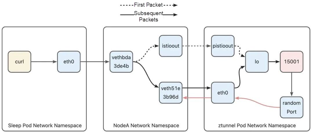
After the packet arrives at Node A, its destination address is the IP address (10.244.1.17) of the httpbin pod, so it hits the pod net segment routing rule added by Kubernetes in the main routing table:
......
10.244.1.0/24 via 172.18.0.4 dev eth0
......
This rule indicates that packets destined for the 10.244.1.0/24 network segment are sent to gateway 172.18.0.4 (Node B address) through eth0 device, and the address of packets sent by the Ztunnel pod are httpbin pod address 10.244.1.7. Therefore, this rule will be hit, leaving Node A through the eth0 device to go to Node B, and finally entering Node B network namespace through the eth0 device of Node B:
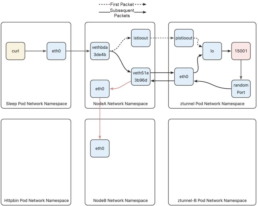
On the node-to-Ztunnel path in the inbound phase, similar to the outbound phase, the first packet and the following packets (TCP handshake packet) will be forwarded to Ztunnel via different paths. Similarly, let's start with the first packet and look at the policy-based routing rules of Node B. Since this packet does not carry any marks and is not in the ztunnel-pod-ips ipset of Node B, at the same time, the destination address of the packet is a pod IP address and will not hit the iptables rules in the Kubernetes network, let's look directly at the policy-based routing phase:
0:      from all lookup local
100:    from all fwmark 0x200/0x200 goto 32766
101:    from all fwmark 0x100/0x100 lookup 101
102:    from all fwmark 0x40/0x40 lookup 102
103:    from all lookup 100
32766:  from all lookup main
32767:  from all lookup default
Since the local routing tables are full of local routing rules, they cannot be hit. The data packet does not have any mark and will not hit routing table 100, 101 or 102. Therefore, the data packet will hit rule 103 and use routing table 100. Next, let's look at the contents of this routing table:
10.244.1.3 dev vethbcda8cd4 scope link
10.244.1.5 via 192.168.126.2 dev istioin src 10.244.1.1
10.244.1.6 via 192.168.126.2 dev istioin src 10.244.1.1
10.244.1.7 via 192.168.126.2 dev istioin src 10.244.1.1
A routing rule is configured for the IP address of each pod running on the node in routing table 100. Each routing rule points to the istioin device on the node. In other words, when the routing table is used for routing, if the destination address of the packet is a pod on the local host, the packet is routed to the istioin device. If the destination address of this packet is httpbin pod address 10.244.1.7, the routing rule in line 4, 10.244.1.7 via 192.168.126 dev istioin src 10.244.1.1, will be hit, and then the packet will enter the istioin device. We mentioned the istioout device in the previous discussion. Similarly, the istioin device is used to process inbound traffic, and the other end is the pistioin device in the Ztunnel B pod.
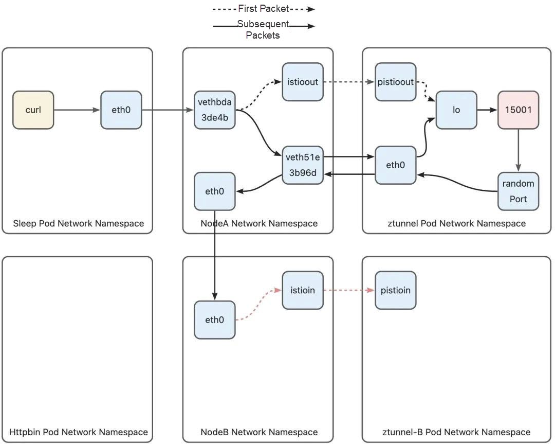
After the data packet enters the Ztunnel B through the pistioin device, as the destination address is the httpbin pod, it also needs to be redirected through iptables rules to avoid being discarded by the Ztunnel pod. Since the destination address of the data packet is port 15008, the data packet will hit the following rule:
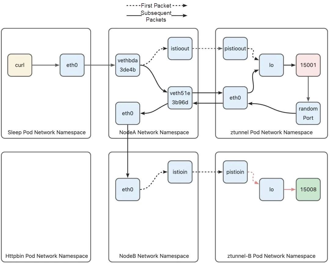
-A PREROUTING -i pistioin -p tcp -m tcp --dport 15008 -j TPROXY --on-port 15008 --on-ip 127.0.0.1 --tproxy-mark 0x400/0xfffThis rule matches a packet from the pistioin device. The protocol is TCP, and the destination port is 15008. Redirect the packet to port 15008 (127.0.0.1) through TPROXY. At the same time, mark the packet with 0 x 400. After the packet is marked, the following rule will be hit in the policy-based routing phase:
20000: from all fwmark 0x400/0xfff lookup 100The policy-based routing rule indicates that the routing table 100 is used to route packets:
local default dev lo scope hostSimilar to Ztunnel A, routing table 100 has only one routing rule, that is, routing the packet to the lo device and forcing the packet to enter the native protocol stack. Since the destination address of the packet is modified by TPROXY to port 15008, the packet will eventually reach the socket that the Ztunnel process is listening on port 15008. At this point, the packet from Ztunnel A successfully reaches the Ztunnel process:
After the Ztunnel pod protocol stack sends a downlink packet, the packet will enter the host through the eth0 device and hit the following iptables rule on the host:
-A ztunnel-PREROUTING ! -s 10.244.2.3/32 -i veth51e3b96d -j MARK --set-xmark 0x210/0x210The matching condition of this rule is that if the source address of the data packet is not the Ztunnel pod IP address and comes from the Ztunnel pod veth device, it is marked with 0 x 210. Similar to the outbound phase, the data packet marked with 0 x 210 will be routed using the main routing table:
100:    from all fwmark 0x200/0x200 goto 32766
......
32766:  from all lookup main
The destination address of the downlink packet is the sleep pod address (10.244.2.8). Therefore, in the main routing table, the packets destined for the 10.244.2.0/24 address range will leave through the eth0 device of the host and be routed to the host where the peer pod resides by the router in the host network by using the routing rules of the Kubernetes network.
10.244.2.0/24 via 172.18.0.3 dev eth0After the routing is determined, the following rules in the ztunnel-FORWARD chain are hit:
-A ztunnel-FORWARD -m mark --mark 0x210/0x210 -j CONNMARK --save-mark --nfmask 0x210 --ctmask 0x210Similar to the outbound phase, on Node A, the connection is marked with 0 x 210 through the reply packet, and the marks on the connection will cause subsequent packets to hit other rules.
Since the connection is marked with 0 x 210, subsequent packets will hit the following iptables rules after entering Node-B:
-A ztunnel-PREROUTING ! -i vethbcda8cd4 -m connmark --mark 0x210/0x210 -j MARK --set-xmark 0x40/0x40
-A ztunnel-PREROUTING -m mark --mark 0x200/0x200 -j RETURN
Similar to Node-A, if the packet does not come from Ztunnel veth and is marked with the 0 x 210 connection mark, the packet is marked with 0 x 40 in order to allow the packet to be routed using routing table 102 in the following routing stages:
102: from all fwmark 0x40/0x40 lookup 102The routing table 102 is a routing table leading to Ztunnel B. The packet will hit the default routing rule and be routed to vethbcda8cd4 (that is, the network device ztunnel-B on the host), thus entering the Ztunnel pod.
default via 10.244.1.3 dev vethbcda8cd4 onlink
10.244.1.3 dev vethbcda8cd4 scope link
The process of entering the Ztunnel pod is the same as that of the inbound phase.
The inbound phase of Node B is similar to the outbound phase of Node A. In the phase from Node-B to Ztunnel, the first packet leaves the host from the istioin interface and enters the Ztunnel pod from the pistioin interface. However, subsequent packets leave the host through the veth device of the Ztunnel pod and then enter the Ztunnel pod through the eth0 device of the Ztunnel pod as connections are marked with 0 x 210.
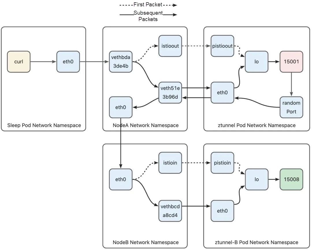
Once Ztunnel B receives the connection from the peer Ztunnel, it immediately establishes a TCP connection to the target pod. This allows the decrypted data to be sent to the target pod through this connection. Ztunnel B retrieves the original destination address from the connection by using the SO_ORIGINAL_DST option with getsockopt. Additionally, it learns the actual target port through the HTTP CONNECT handshake message sent by Ztunnel A. At the same time, in order to make the httpbin pod believe that the data packet originates from the sleep pod, Ztunnel must forcibly set the source address of the connection to the address of the sleep pod using the IP_TRANSPARENT option on the socket used to connect to httpbin. Ztunnel can obtain the address of the sleep pod based on the source address of the connection. As a result, the source address of the packet sent from Ztunnel B is the sleep pod's address, and the destination address is the httpbin pod's address, mimicking as if the packet was actually sent from the sleep pod. Now, let's explore how this packet exits the Ztunnel pod and ultimately reaches the httpbin pod.
Since the packet destined for the httpbin pod does not match any iptables rules within any Ztunnel B pod, the pod does not have any associated marks. The packet will encounter the following policy-based routing within the Ztunnel pod. The main routing table is used for routing.
0:      from all lookup local
20000:  from all fwmark 0x400/0xfff lookup 100
20003:  from all fwmark 0x4d3/0xfff lookup 100
32766:  from all lookup main
32767:  from all lookup default
The contents of the main routing table are as follows:
default via 10.244.1.1 dev eth0
10.244.1.0/24 via 10.244.1.1 dev eth0 src 10.244.1.3
10.244.1.1 dev eth0 scope link src 10.244.1.3
192.168.126.0/30 dev pistioin proto kernel scope link src 192.168.126.2
192.168.127.0/30 dev pistioout proto kernel scope link src 192.168.127.2
Since the address of the httpbin pod is 10.244.1.7, the default rule, default via 10.244.1.1 dev eth0, in the routing table is used for routing, and the packet will be sent to the eth0 network interface to leave the Ztunnel pod and enter the host.
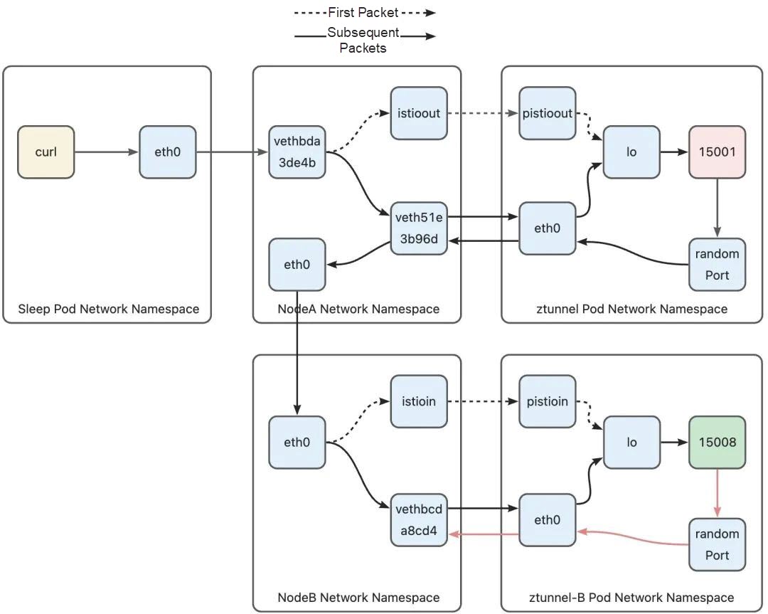
After the data packet arrives at the host, its destination address is the address of the pod on the host, so it needs to avoid hitting the routing rule of redirecting the data packet to the Ztunnel pod hit in the previous phase. Ambient Mesh has added the following rule to the ztunnel-PREROUTING chain (refer to the previous section to see how to jump to the ztunnel-PREROUTING chain, which will not be repeated here):
......
-A ztunnel-PREROUTING ! -s 10.244.1.3/32 -i vethbcda8cd4 -j MARK --set-xmark 0x210/0x210
......
Vethbcda8cd4 is the device of Ztunnel B pod's veth pair on the host side. After the data packet enters the eth0 device of the Ztunnel pod, it is through this device that it reaches the host. This rule matches the data packet from the Ztunnel pod veth. The data packet that hits this rule will be marked with 0 x 210. In the second part, the data packet from Ztunnel A hits the policy-based routing rule numbered 103. Routing table 100 is used to route the packet to the Ztunnel pod. However, the current packet will hit the policy-based routing rule numbered 100 because it is marked with 0 x 210. Finally, the main routing table is used for routing.
0:      from all lookup local
100:    from all fwmark 0x200/0x200 goto 32766
101:    from all fwmark 0x100/0x100 lookup 101
102:    from all fwmark 0x40/0x40 lookup 102
103:    from all lookup 100
32766:  from all lookup main
32767:  from all lookup default
Let's take a look at the contents of the main routing table:
default via 172.18.0.1 dev eth0
10.244.0.0/24 via 172.18.0.2 dev eth0
10.244.1.2 dev veth1eb71e57 scope host
10.244.1.3 dev vethbcda8cd4 scope host
10.244.1.5 dev veth6cba8664 scope host
10.244.1.6 dev vetheee0622e scope host
10.244.1.7 dev vethfc1b555e scope host
10.244.2.0/24 via 172.18.0.3 dev eth0
172.18.0.0/16 dev eth0 proto kernel scope link src 172.18.0.4
192.168.126.0/30 dev istioin proto kernel scope link src 192.168.126.1
The Kubernetes network will insert entries of all pod routes on the current node into the main routing table. The packet destined for the pod IP address will be routed to the veth device connected to the pod network namespace. This packet destined for the httpbin pod will hit the routing rule in line 7 and will be routed to the vethfc1b555e device, and then the packet will enter the httpbin pod from the other end of the device - the eth0 device located in the httpbin pod. At this point, we have understood the full path of the packet.
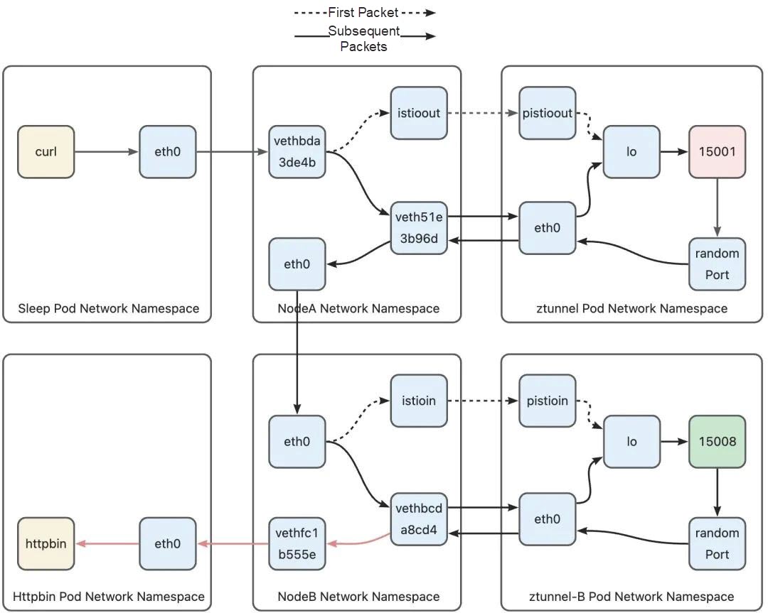
In this article, I have analyzed the complete path from the source pod to the target pod in Ambient Mesh. However, due to space limitations, some details have not been mentioned, such as packet routing for non-pod communication. I will gradually share these contents in future discussions.
Alibaba Cloud Service Mesh (ASM) [2] supports the Ambient mode in 1.18 and later version. As the industry's first fully managed service mesh that supports the Ambient mode, ASM has adapted common network plugins and provides corresponding documentation, including routing rules and security rules, for the Ambient mode. You are welcomed to try ASM.
[1] Article
https://www.alibabacloud.com/blog/analysis-of-the-implementation-of-layer-4-load-balancing-in-istio-ambient-mesh_600642
[2] Alibaba Cloud Service Mesh (ASM):
https://www.alibabacloud.com/product/servicemesh
Analysis of the Implementation of Layer 4 Load Balancing in Istio Ambient Mesh

640 posts | 55 followers
FollowAlibaba Cloud Native Community - December 18, 2023
Alibaba Container Service - August 16, 2024
Alibaba Cloud Native Community - December 15, 2023
Alibaba Container Service - September 18, 2025
Alibaba Container Service - September 11, 2025
Alibaba Cloud Native Community - December 11, 2023

640 posts | 55 followers
Follow Alibaba Cloud Service Mesh
Alibaba Cloud Service Mesh (ASM) is a fully managed service mesh platform that is compatible with Istio.
Learn More Cloud-Native Applications Management Solution
Accelerate and secure the development, deployment, and management of containerized applications cost-effectively.
Learn More Elastic Desktop Service
A convenient and secure cloud-based Desktop-as-a-Service (DaaS) solution
Learn More IDaaS
IDaaS
Make identity management a painless experience and eliminate Identity Silos
Learn MoreMore Posts by Alibaba Cloud Native Community