By Hanzhi
Nowadays, the disk database will record REDO and UNDO logs, namely the ARIES method, to ensure the atomicity (abbreviated as "A") and durability (abbreviated as "D") of the database and make full use of the performance of disk sequential write with a flexible flushing disk strategy. This article will focus on several aspects of REDO logs, including the role, recorded content, organizational structure, and writing methods. I hope this article will help readers understand the role of REDO logs in InnoDB. This article is based on the code of MySQL 8.0.
InnoDB caches data in the memory (InnoDB Buffer Pool) to achieve better read and write performance. The modification of data in disks lags behind the memory. Thus, if the process or machine crashes, the memory data will be lost. InnoDB maintains REDO logs to ensure the consistency and durability of the database. Before modifying the Page, we need to record the modified content in REDO logs and ensure they are written to disk earlier than the corresponding Page. We call this Write Ahead Log (WAL). When a fault occurs and causes memory data loss, InnoDB replays REDO logs to restore the Page to its pre-crash state when InnoDB restarts.
What kind of REDO logs do we need? First, the maintenance of REDO logs adds a copy of writing data. Meanwhile, to make the data correct, the transaction can only return to the user when all of its REDO logs are written to the disk. The write time of REDO logs directly affects the system throughput. Thus, the data in REDO logs should be as small as possible. Second, a system crash occurs unexpectedly. When REDO logs are replayed, the system does not know which corresponding Pages of REDO logs have been written to the disk. Therefore, REDO log replay must be reentrant. That means the REDO operation must be idempotent. Third, REDO logs should be Page-based to speed up recovery after restarting through concurrent replay. That means one REDO log only involves the modification of one Page.
Regular readers will find that small data volume is the advantage of Logical Logging, while idempotence and Page-based are the advantages of Physical Logging. InnoDB adopts a method called Physiological Logging to acquire the advantages of the two. The so-called Physiological Logging is based on Pages while being recorded logically within Page. The following example is a modification to one Record in Page recorded in a REDO log of MLOG_REC_UPDATE_IN_PLACE type:
(Page ID, Record Offset, (Field 1, Value 1) ... (Field i, Value i) ... )
Among them, Page ID specifies the Page to be operated, Record Offset records the offset position of Record in Page, and the field array records the Field to be modified and the modified Value.
Since the Physiological Logging method uses the logical notation in the physical Page, two problems are caused.
Since the REDO log records the two modifications logically within a Page, a replay of the REDO log must be based on the correct Page state. However, the default Page size of InnoDB is 16 KB, but the file system can only guarantee the atomicity of a file up to 4 KB. As a result, only half of the Page content may be successfully recovered. InnoDB uses Double Write Buffer to find a correct Page state during recovery by writing twice. We will elaborate on this topic when introducing Buffer Pool later.
Double Write Buffer can find a correct Page state. We also need to know which record in the REDO log this state corresponds to to avoid repeated modification of the Page. For this purpose, InnoDB gives each REDO record a globally unique incremental label: Log Sequence Number (LSN). When the Page is modified, the LSN of the corresponding REDO record will be recorded in the FIL_PAGE_LSN field of the Page. This way, when REDO replay continues, the REDO log that has been applied can be skipped, thus realizing the idempotence of replay.
We know how REDO logs are recorded in InnoDB, but what is recorded in REDO logs? There have been 65 types of REDO records by MySQL 8.0 to meet various requirements of InnoDB. They are used to record different information. When recovering, we need to determine different REDO types for corresponding resolution. According to the different objects corresponding to REDO records, the 65 types of REDO records can be divided into three categories: REDO for Page, REDO for Space, and the Logic type that provides additional information.
This REDO type accounts for the vast majority of all REDO types. It can be subdivided into Index Page REDO, Undo Page REDO, and Rtree PageREDO. For example, MLOG_REC_INSERT, MLOG_REC_UPDATE_IN_PLACE, and MLOG_REC_DELETE correspond to the insertion, modification, and deletion of records ofthe Page, respectively. Let's take MLOG_REC_UPDATE_IN_PLACE as an example:
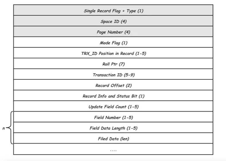
Type is MLOG_REC_UPDATE_IN_PLACE, and Space ID and Page Number uniquely identify a Page. These three items are header information that all REDO records must have. The following items are unique to MLOG_REC_UPDATE_IN_PLACE. Among them, Record Offset gives the position offset of the record to be modified in Page. Update Field Count indicates how many Fields need to be modified in the record. Then, values of Field Number, Field Data Length, and Field Data are given for each Field.
This type of REDO log modifies a Space file. For example, MLOG_FILE_CREATE, MLOG_FILE_DELETE, and MLOG_FILE_RENAME correspond to the creation, deletion, and renaming of a Space, respectively. The REDO logs of the file operation are only recorded after the file operation is completed. So, when such logs are seen during recovery, it means the file operation is successful. Therefore, most of the files are only checked during the recovery process. Let's take MLOG_FILE_CREATE as an example:

Similar to MLOG_REC_UPDATE_IN_PLACE, the first three fields are Type, Space ID, and Page Number. Since the REDO logs are for Space, the Page Number here is always 0. The following fields record the created file flag and the file name used for check during restart.
In addition to the types above, a few REDO types do not involve specific data modifications but only record some required information. For example, the most common MLOG_MULTI_REC_END is used for identifying a REDO group, which means it indicates the end of a complete atomic operation.
The so-called organization method of REDO logs is how to record the required REDO contents into disk files to facilitate efficient REDO writing, reading, recovery, and cleaning. Here, REDO logs are divided into three layers from top to bottom: logical REDO layer, physical REDO layer, and file layer.
This layer is the real REDO content. REDO logs consist of multiple closely connected REDO records of different Types with globally unique incremental offsets sn. InnoDB maintains the maximum value of the current sn in the global log_sys and increases the sn to the REDO content length each time data is written, as shown in the following figure:

Disk is a block device. InnoDB also uses the concept of Block to read and write data. The length of a Block is OS_FILE_LOG_BLOCK_SIZE, which equals the size of the disk sector of 512 B. The minimum unit for each I/O read and write is a Block. In addition to REDO data, Block needs some additional information. The composition of a Log Block is shown in the following figure. It includes a 12-byte Block Header. In Block Header, Flush Flag occupies the highest bit in the first four bytes for identifying the first Block of an I/O, and the remaining 31 bits are for the Block number. The following 2 bytes indicate the data length with a value range of [12, 508]. The next 2-byte First Record Offset points to the beginning of the first REDO group in the Block. This value enables us to find a valid REDO start position for any Block. The last 4-byte Checkpoint Number records the next_checkpoint_number when writing Block and is used to discover the circular use of files. This will be elaborated on in the File Layer part. The end of the Block is a 4-byte Block Tailer, which records the Checksum of the current Block. Through this value, we can determine whether the Block data has been completely written when reading Log.
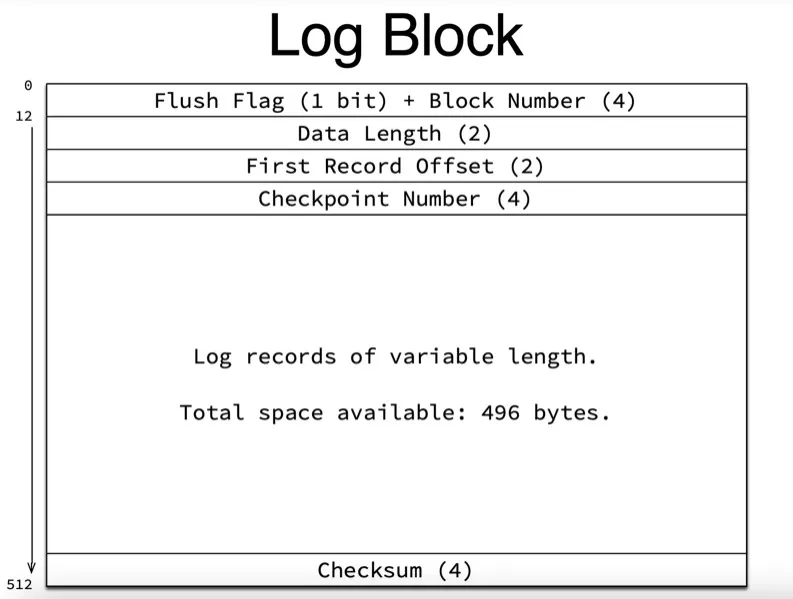
The remaining 498 bytes in the middle in Block are the storage location where the contents of REDO logs are really stored. This is the logical REDO we mentioned earlier. Now, let's put the logical REDO into the physical REDO space. Since the space in the Block is fixed, and the REDO length is variable, there may be multiple REDO logs in one Block, or one REDO log may be split to be stored in multiple Blocks. As shown in the following figure, the brown and red parts represent Block Header and Tailer, respectively. The REDO record in the middle is split and stored in two consecutive Blocks as the space left by the previous Block is insufficient.

Due to the increased byte overhead of Block Header and Tailer, LSN is used to identify the offset in the physical REDO space. There is a simple conversion relationship between LSN and SN:
constexpr inline lsn_t log_translate_sn_to_lsn(lsn_t sn) {
  return (sn / LOG_BLOCK_DATA_SIZE * OS_FILE_LOG_BLOCK_SIZE +
          sn % LOG_BLOCK_DATA_SIZE + LOG_BLOCK_HDR_SIZE);
}
You can obtain corresponding LSN through SN and length of Headers and Trailers of all previous Blocks and vice versa.
Finally, REDO is written to the REDO log file (named ib_logfile0, ib_logfile1, etc.) to avoid the overhead caused by file creation and space initialization, and the REDO file of InnoDB is recycled. You can specify the number of REDO files through the parameter innodb_log_files_in_group. Multiple files write REDO content consecutively. Each file is divided by Block. At the beginning of each file, four Blocks are reserved for recording some additional information. The first Block is called Header Block. The next three Blocks are used to store Checkpoint information in the No.0 file while being left blank in other files.
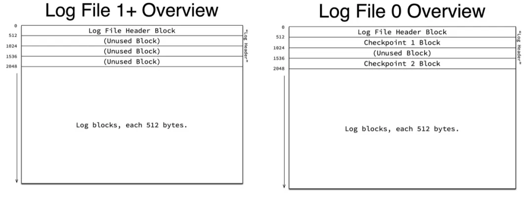
The data area of the first Header Block records some file information. As shown in the following figure, the 4-byte Formate field records the version of Log. Their REDO types are different for different versions of Logs. This information is added starting from MySQL 8.0. The 8-byte Start LSN identifies the start LSN of the current file, through which the offset of the file can correspond to the corresponding LSN. Finally, Creator information (0-32 bits) is recorded. Normally, the MySQL version is also recorded.

Now, we put REDO into the file space. As shown in the following figure, logical REDO is the needed data. With sn index, logical REDO is organized according to fixed-sized Blocks, and the head and tail information of Blocks is added to form physical REDO. With the lsn index, these Blocks will be placed in a certain position in the file space that is recycled. These Blocks are indexed with offset in the file space.
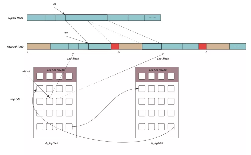
Although LSN can uniquely identify a REDO location, the final read and write of REDO needs to be converted to the read and write I/O of files. At this time, the offset that can express file space is needed. The following code shows the conversion process between them:
const auto real_offset =
   log.current_file_real_offset + (lsn - log.current_file_lsn);
When switching files, the file offset (current_file_real_offset) at the beginning of the current file and the corresponding LSN (current_file_Isn) will be updated in the memory. With these two values, we can convert LSN into file offset through the equation above. Note: The offset here is referred to in terms of the entire REDO file space. Since the InnoDB implementation of reading and writing files in the space layer supports multiple files, multiple REDO files connected can be regarded as a large file. Then, the offset here is the offset in this large file.
As important information to maintain the correctness of the database, REDO logs must be written to the disk before the transaction is committed. Otherwise, data may be lost once the power is cut off. Therefore, the complete process from REDO generation to final writing becomes the key path for database writing, and its efficiency determines the writing performance of the database. This process includes generating REDO content, writing REDO to InnoDB Log Buffer, writing from InnoDB Log Buffer to the Page Cache of the operating system, and flushing REDO to the disk. After that, we need to wake up the waiting user thread to commit the transaction. Now, let's look at how InnoDB can efficiently write REDO logs under the condition of high concurrency in these stages.
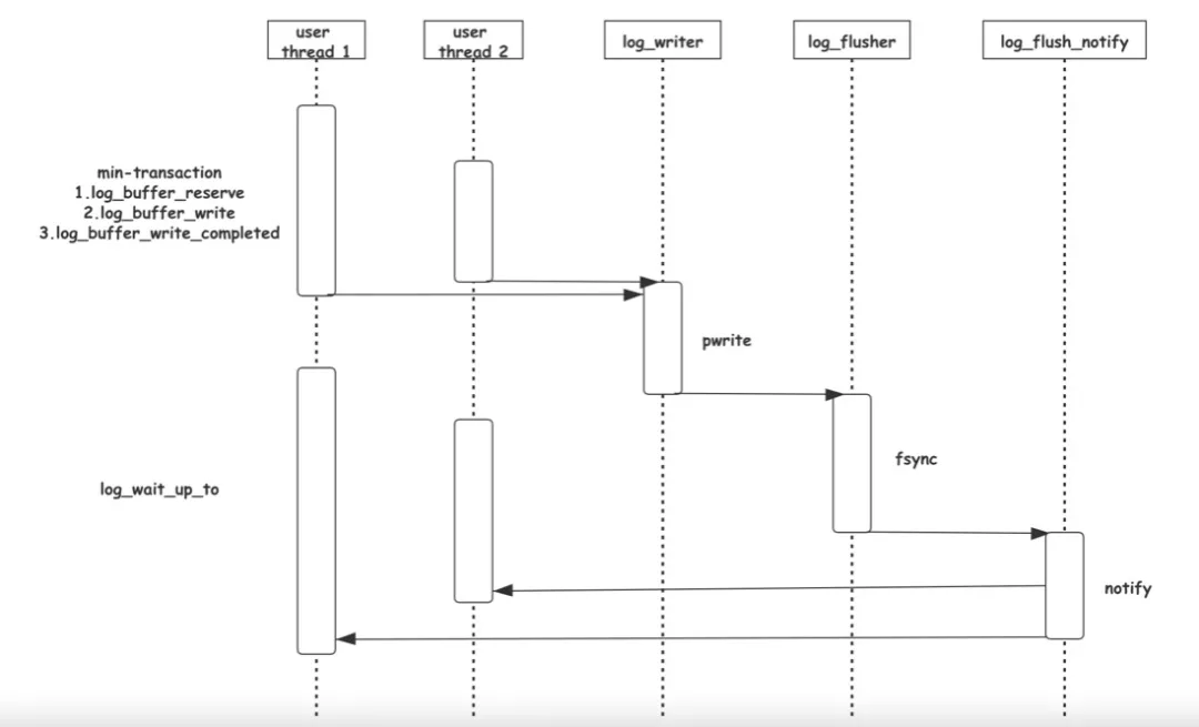
We know transactions will generate REDO records when writing data. An atomic operation may contain multiple REDO records. These REDO records may refer to access to different locations on the same Page or different Pages (such as Btree node splitting). InnoDB has a complete set of mechanisms to ensure the atomicity of multiple REDO records involved in one atomic operation. In other words, they are either all replayed or not replayed during recovery. This will be elaborated on when we introduce recovery logic later. This article only touches on the most basic requirement: these REDO records must be continuous. InnoDB achieves this goal by min-transaction (MTR). When an atomic operation is required, mtr_start is called to generate an MTR. MTR maintains a dynamically growing m_log, a dynamically allocated memory space. All REDO records that need to be written by this atomic operation are written to this m_log first. When the atomic operation is completed, mtr_commit is called to copy the data in m_log to the Log Buffer of InnoDB.
In a high-concurrency environment, there are a lot of min-transactions (MTR) that need to copy data to Log Buffer at the same time. If mutex lock is involved, this will become a performance bottleneck. As a result, starting from MySQL 8.0, a lock-free log writing mechanism has been designed. Its core idea is to allow different MTR to concurrently write different positions of Log Buffer. Different MTR will call the log_buffer_reserve function first. This function uses its REDO length to atomically perform fetch_add operation on the global offset log.sn to obtain its exclusive space in Log Buffer. Then, different MTR copy the data in their m_log to their exclusive spaces in parallel.
/* Reserve space in sequence of data bytes: */
const sn_t start_sn = log.sn.fetch_add(len);REDO data written to Log Buffer needs to be written to the Page Cache of the operating system. InnoDB uses a separate log_writer to do this, but there is a problem. Since the data in Log Buffer is written concurrently by different MTR, there is a hole in the Log Buffer in this process. Therefore, log_writer needs to sense the end of the continuous logs in the current Log Buffer and write the continuous logs to the Page Cache of the operating system through the pwrite system call. In the whole process, data copying of the subsequent MTR should not be affected as much as possible. For this purpose, InnoDB introduces a data structure called link_buf, as shown in the following figure:
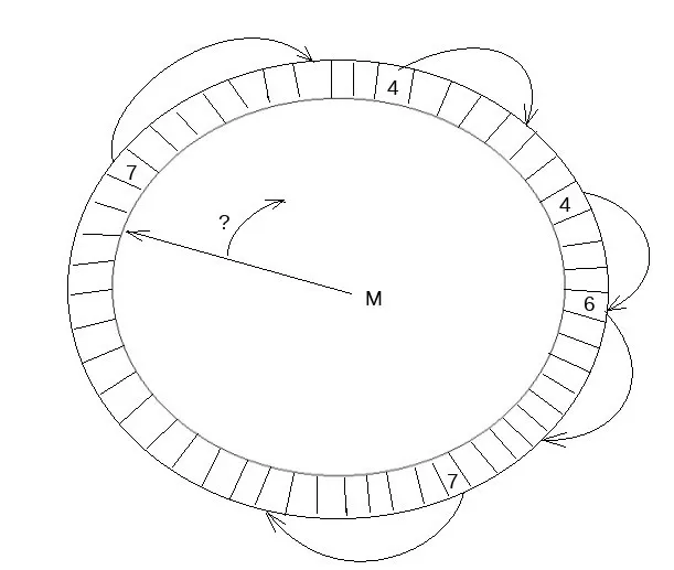
Link_buf is an array that is used in a loop. We can obtain its slot position on link_buf by performing a modulo operation on each LSN. This slot position records the REDO length. Another thread traverses the link_buf from the beginning. With REDO length recorded in the slot position, we can find the end position of the REDO record. The thread traverses to the next position where the value is 0. Then, we can consider that the next REDO has a hole, and the previous REDO is continuous. This position is called the tail of link_buf. Now let's take a look at how log_writer and numerous MTR take advantage of link_buf. The link_buf here is the log.recent_written, as shown in the following figure:

The upper part of the figure shows the schematic diagram of the REDO log. write_lsn is the end of the log that has been written to the Page Cache by the current log_writer. current_lsn is the maximum LSN position that has been allocated to MTR currently, and buf_ready_for_write_lsn is the end of the continuous log in the Log Buffer found by the current log_writer. The range from write_lsn to buf_ready_for_write_lsn is the range where the next log_writer can continuously call pwrite to write to the Page Cache. The range from buf_ready_for_write_lsn to current_lsn is the range where the current MTR concurrently writes Log Buffer. The following continuous grids show the data structure of log.recent_written. We can see that the buf_ready_for_write_lsn cannot advance due to the two all-zero holes in the middle. Now, suppose that the MTR from reserve to the first hole in the middle also completes writing Log Buffer and updates the log.recent_written*, as shown in the following figure:

At this time, log_writer traverses the log.recent_written backward from the current buf_ready_for_write_lsn and finds that this section is continuous.

Therefore, the current buf_ready_for_write_lsn and the tail position of log.recent_written move forward, while the subsequent position is cleared for cyclic reuse.

Then, log_writer flushes consecutive content to disk and improves write_lsn.
After log_writer improves write_lsn, it notifies the log_flusher thread. The log_flusher thread calls fsync to flush the REDO records to the disk, thus finishing the complete REDO write process.
Transactions can only be committed after REDO writes are completed to ensure data correctness. Therefore, many user threads will be blocked and wait until their last logs are written during REDO writes. innodb_flush_log_at_trx_commit = 1 by default, and you need to wait for REDO records to be flushed. This is also the safest way. You can also set innodb_flush_log_at_trx_commit = 2. This way, as long as REDO records are written to the Page Cache, the write is considered to be completed. In extreme cases, power failure may cause data loss.
Many user threads call log_write_up_to to wait in their LSN positions. InnoDB splits the blocked condition variable into multiple variables to avoid many invalid wake ups. According to the block where the Isn that it needs to wait is located, log_write_up_to performs a modulo operation on the block to correspond to the different condition variables. At the same time, InnoDB introduces two threads specifically responsible for waking up users (log_wirte_notifier and log_flush_notifier) to avoid a large number of wake up work affecting log_writer or log_flusher threads. When more than one condition variable needs to be wakened up, log_writer and log_flusher will notify these two threads to complete the wake up work. The following figure shows the entire process.
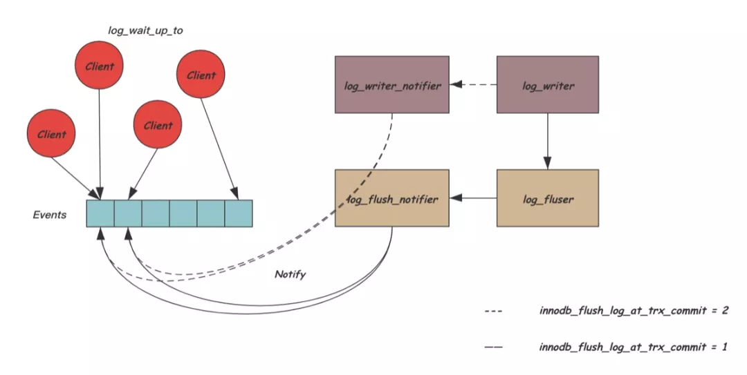
multiple threads have efficiently completed the process from REDO generation and REDO disk writing to waking up user threads through the assistance of some internal data structures. The following figure is a sequence diagram of the entire process:
As the space of REDO files is limited, InnoDB introduces log checkpointer threads to periodically generate Checkpoint and minimize REDO that needs to be replayed during recovery. When restarting for recovery, we only need to start replaying the REDO after the latest Checkpoint. Therefore, REDO before the checkpoint can be deleted or reused.
We know REDO is used to prevent the data that is only written to the memory from being lost due to failure. Therefore, the location of Checkpoint must ensure all the dirty memory pages generated by REDO have been flushed. The minimum REDO LSN (lwm_lsn) corresponding to all dirty pages can be obtained from Buffer Pool. This is the easiest way. However, this alone is not enough because some of the corresponding Page of min-transaction REDO has not yet been added to the dirty page of Buffer Pool. If the checkpoint is added to the back of these REDO records, this part of data will be lost once the failure recovery occurs. Therefore, we also need to know the REDO LSN position (dpa_lsn) currently added to Buffer Pool. We will take the smaller value of the two as the final checkpoint position. The following code shows the core logic:
/* LWM lsn for unflushed dirty pages in Buffer Pool */
lsn_t lwm_lsn = buf_pool_get_oldest_modification_lwm();

/* Note lsn up to which all dirty pages have already been added into Buffer Pool */
const lsn_t dpa_lsn = log_buffer_dirty_pages_added_up_to_lsn(log);

lsn_t checkpoint_lsn = std::min(lwm_lsn, dpa_lsn);
In MySQL 8.0, concurrently registering dirty pages for Buffer Pool is allowed to achieve higher concurrency between MTR. Similar to log.recent_written and log_writer, a link_buf called recent_closed is introduced here to handle the holes caused by concurrency. A separate thread log_closer promotes the tail of recent_closed, which is the maximum LSN continuously added to the dirty page of Buffer Pool. This value is also the dpa_lsn mentioned above. Due to this disorder, the value of lwm_lsn cannot obtain the LSN of the oldest dirty page in the current Buffer Pool. It is necessary to subtract the capacity size of recent_closed (the largest disorder range) for accuracy consideration. The simplified code is shown below:
/* LWM lsn for unflushed dirty pages in Buffer Pool */
const lsn_t lsn = buf_pool_get_oldest_modification_approx();
const lsn_t lag = log.recent_closed.capacity();
lsn_t lwm_lsn = lsn - lag;

/* Note lsn up to which all dirty pages have already been added into Buffer Pool */
const lsn_t dpa_lsn = log_buffer_dirty_pages_added_up_to_lsn(log);

lsn_t checkpoint_lsn = std::min(lwm_lsn, dpa_lsn);
There is a problem. Since lwm_lsn has subtracted the capacity of recent_closed, theoretically, this value must be less than dpa_lsn. Then, it may be meaningless to compare lwm_lsn and dpa_lsn to obtain the Checkpoint position.
As mentioned above, two of the first three Blocks of the ib_logfile0 file are reserved as Checkpoint Blocks. These two Blocks will be used alternatively when generating Checkpoints. This is to avoid crashes during writing Checkpoints resulting in no available Checkpoints. The following chart is the content in Checkpoint Block:

The 8-byte Checkpoint Number can be used to determine the latest Checkpoint record by comparing this value. Then, the 8-byte Checkpoint LSN is the REDO position of the generated checkpoint. During recovery, the REDO starting from this position will be replayed. The next 8-byte Checkpoint Offset makes the Checkpoint LSN correspond to the offset of the file space. The last 8 bytes indicate the length of the Log Buffer mentioned earlier. This value is currently not used in the recovery process.
This article introduces the function, features, organizational structure, writing methods, and cleanup timing of REDO in InnoDB, which covers most of the contents of REDO. The way to restore the database to the correct state during restart using REDO will be elaborated later when we introduce the failure recovery mechanism of InnoDB.
[1] MySQL 8.0.11 Source Code Documentation: Format of REDO log
https://dev.mysql.com/doc/dev/mysql-server/8.0.11/PAGE_INNODB_REDO_LOG_FORMAT.html
[2] MySQL 8.0: New Lock free, scalable WAL design
https://mysqlserverteam.com/mysql-8-0-new-lock-free-scalable-wal-design/
[3] How InnoDB handles REDO logging
https://www.percona.com/blog/2011/02/03/how-innodb-handles-redo-logging/
[4] MySQL Source Code
https://github.com/mysql/mysql-server
[5] Past and Present of the Recovery Mechanism of Database Failure
http://catkang.github.io/2019/01/16/crash-recovery.html
ApsaraDB - June 1, 2022
ApsaraDB - May 29, 2024
Alibaba Clouder - August 26, 2021
ApsaraDB - February 22, 2023
Alibaba Clouder - December 2, 2016
ApsaraDB - April 9, 2025
 PolarDB for MySQL
Alibaba Cloud PolarDB for MySQL is a cloud-native relational database service 100% compatible with MySQL.
Learn More AnalyticDB for MySQL
AnalyticDB for MySQL is a real-time data warehousing service that can process petabytes of data with high concurrency and low latency.
Learn More Storage Capacity Unit
Plan and optimize your storage budget with flexible storage services
Learn More Hybrid Cloud Storage
A cost-effective, efficient and easy-to-manage hybrid cloud storage solution.
Learn MoreMore Posts by ApsaraDB