This topic describes how to configure an Internet network address translation (NAT) gateway to connect a self-managed Internet-facing database to Alibaba Cloud and configure a Data Transmission Service (DTS) instance over a virtual private cloud (VPC).
Background information
When you create a DTS instance where the source or destination database is accessible over the Internet, and set the Access Method parameter to Public IP Address, you must add the CIDR block of the DTS server to the security settings of the database, such as firewall policies, IP address whitelists, and security group rules. A DTS server may use a large number of IP addresses and the IP addresses may change as your business develops. Some IP addresses may be missed or you cannot connect to the database due to an invalid IP address. In this case, an error occurs to an instance.
Prerequisites
The database can access the Internet.
Procedure
Create a VPC.
Create a transit VPC and a vSwitch.
Purchase an Internet NAT gateway.
Purchase an Internet NAT gateway in the transit VPC.
Purchase an elastic IP address (EIP).
Associate the EIP to the Internet NAT gateway.
Configure SNAT entries to the Internet NAT gateway.
Configure alert rules in the Cloud Monitor console.
Configure alert rules for the EIP associated with the Internet NAT gateway to monitor metrics and handle exceptions at the earliest opportunity.
Configure the database whitelist.
Add the EIP to the security settings of the database.
Create a DTS instance.
Usage notes
You are charged for the Internet NAT gateway and EIP purchased. For more information, see Billing of Internet NAT gateways and Billing methods.
The instance in this solution may be unstable due to factors such as poor quality of Internet connections. Issues that arise in such circumstance are not covered by the service level agreement (SLA) of DTS.
When the DTS instance in this solution is running, do not modify or delete the transit VPC, the Internet NAT gateway, or associated EIP. Otherwise, the DTS instance is delayed or interrupted.
The IP address whitelist of the database connected over the Internet includes all EIPs associated with the In ternet NAT gateway. This way, you can access the database by using the Internet NAT gateway.
Do not add IP addresses beyond the EIP to the IP address whitelist of the database. Otherwise, this poses security risks to the database such as unauthorized access from other public IP addresses.
You can specify the Maximum Bandwidth parameter based on your business requirements when you purchase the EIP.
NoteEach DTS thread has only one connection that accesses the database by using an EIP.
You must disable the EIP Affinity of the Internet NAT gateway to ensure that DTS can use all associated EIPs. Otherwise, some associated EIPs fail to be used and the traffic of multiple threads cannot be distributed to multiple EIPs. A traffic bottleneck occurs.
The values of OutboundRatelimitDropSpeed and InboundRatelimitDropSpeed for each EIP associated with the Internet NAT gateway must be 0. If the value is greater than 0, a DTS instance may be delayed or interrupted. To address this issue, you can scale out the traffic (Maximum Bandwidth) of the EIP or increase the number of EIPs associated with the Internet NAT gateway. For more information, see Upgrades and downgrades.
NoteIf you increase the number of EIPs associated with the Internet NAT gateway, you must add the new EIPs to the IP address whitelist of the database connected over the Internet.
If the packet loss still appears after necessary actions are taken, contact the technical support for help.
If SSL encryption is enabled for the database, you may not use this method to connect the database to DTS.
Procedure
Step 1: Create a VPC
Log on to the VPC console.
In the top navigation bar, select the region where you want to create the VPC and vSwitch.
NoteThe VPC and the cloud resources that you want to deploy must belong to the same region.
On the VPC page, click Create VPC, and configure the VPC and vSwitch based on the following information.
Parameter
Description
Region
Displays the region where you want to create the VPC.
IPv4 CIDR Block
Select a method to allocate an IPv4 CIDR block to the VPC.
Manually enter an IPv4 CIDR block: Manually enter an IPv4 CIDR block.
IPv4 CIDR block allocated by IPAM: An IPv4 CIDR block will be allocated from an IP Address Manager (IPAM) pool.
NoteYou can allocate an IPv4 CIDR block from an IPAM pool in the following regions: China (Hangzhou), China (Shanghai), China (Qingdao), China (Beijing), China (Zhangjiakou), China (Hohhot), China (Ulanqab), China (Shenzhen), China (Hong Kong), Singapore, Malaysia (Kuala Lumpur), Philippines (Manila), US (Silicon Valley), and US (Virginia).
Enter an IPv4 CIDR block
Enter a primary IPv4 CIDR block for the VPC.
We recommend using the private IPv4 addresses specified in RFC 1918 as the primary IPv4 CIDR block with a subnet mask from /16 to /28. For example, 10.0.0.0/16, 172.16.0.0/16, and 192.168.0.0/16.
You can also use a custom CIDR block other than 100.64.0.0/10, 224.0.0.0/4, 127.0.0.0/8, 169.254.0.0/16, and their subnets as the primary IPv4 CIDR block.
In scenarios where multiple VPCs are used or in hybrid clouds, make sure that the CIDR blocks do not overlap between different VPCs and between VPCs and data centers.
NoteThis parameter is required only when you set IPv4 CIDR Block to Manually enter an IPv4 CIDR block.
After a VPC is created, you can add secondary IPv4 CIDR blocks to the VPC. For more information, see Create and manage a VPC.
Select Pool
Select an IPAM pool.
NoteThis parameter is required only when you set IPv4 CIDR Block to IPv4 CIDR Block Allocated By IPAM.
Make sure that an effective region is specified for the selected IPAM pool and CIDR blocks are provisioned to the IPAM pool. For more information, see Create an IPAM pool and Provision CIDR blocks.
Network Mask
Select a network mask. This parameter is required only if you set IPv4 CIDR Block to IPv4 CIDR block allocated by IPAM and an IPAM pool is specified in the Select Pool field.
If the selected pool has multiple CIDR blocks, the system selects one that meets the allocation rules after you specify Network Mask.
ImportantThe network mask must fall within the ranges of:
CIDR block of VPC.
Allocation rules of IPAM pool.
Provisioned CIDR blocks of IPAM pool.
For example:
The network mask of the VPC is /16 to /28.
The minimum mask for the IPAM pool is /4 and the maximum is /27.
The provisioned CIDR blocks of IPAM pool include 10.0.0.0/16, 10.16.0.0/17, and 10.20.0.0/18.
Then, the mask length for the IPv4 CIDR block allocated from IPAM pool is /16 to /27.
IPv6 CIDR Block
Specify whether to assign an IPv6 CIDR block to the VPC. In this example, Assign BGP (Multi-ISP) is selected.
If you choose to assign an IPv6 CIDR block, the system automatically creates an IPv6 gateway of Free Edition for this VPC, and assigns one with the subnet mask /56, such as 2408:4005:3c5:6e00::/56. By default, IPv6 addresses are used for communication only within private networks. If you want to use an IPv6 address to access the Internet or provide services for IPv6 clients over the Internet, you must purchase IPv6 Internet bandwidth.
NoteFor information about the regions that support IPv6 CIDR blocks, see Regions that support IPv4/IPv6 dual-stack.
After creating a VPC, you cannot modify its IPv6 CIDR block, but you can add secondary IPv6 CIDR blocks.
vSwitch
Zone
Select a zone for the vSwitch from the drop-down list. In the same VPC, vSwitches in different zones can communicate with each other.
The drop-down list shows whether the following instance types are supported in each zone: Elastic Compute Service (ECS), ApsaraDB RDS, internal-facing Classic Load Balancer (CLB), internal-facing Application Load Balancer (ALB). The supported cloud resources vary based on the zone and the creation time of the cloud resources. Instances provided in this topic are for reference only. The actual instances on the buy page shall prevail.
IPv4 CIDR Block
Enter an IPv4 CIDR block for the vSwitch. When you specify a CIDR block for the vSwitch, take note of the following limits:
The CIDR block of a vSwitch must be a proper subset of the CIDR block of the VPC to which the vSwitch belongs.
For example, if the CIDR block of a VPC is 192.168.0.0/16, the CIDR block of a vSwitch in the VPC can range from 192.168.0.0/17 to 192.168.0.0/29.
The first and last three IP addresses of a vSwitch CIDR block are reserved.
For example, if a vSwitch CIDR block is 192.168.1.0/24, the reserved IP addresses include 192.168.1.0, 192.168.1.253, 192.168.1.254, and 192.168.1.255.
If a vSwitch needs to communicate with vSwitches in other VPCs or with data centers, make sure that its CIDR block does not overlap with the destination ones.
NoteAfter the vSwitch is created, you cannot modify its CIDR block.
IPv6 CIDR Block
Enable IPv6 and configure an IPv6 CIDR block for the vSwitch.
NoteYou need to configure the IPv6 CIDR block for the vSwitch only when an IPv6 CIDR block is assigned to the VPC.
By default, the subnet mask of the IPv6 CIDR block of a vSwitch is /64. Enter a decimal number from 0 to 255 to define the last 8 bits of the IPv6 CIDR block.
For example, if the IPv6 CIDR block of the VPC is 2408:XXXX:XXXX:6e00::/56, enter 255 (ff in hexadecimal format) for the IPv6 CIDR block of the vSwitch. In this case, the IPv6 CIDR block of the vSwitch is 2408:XXXX:XXXX:6eff::/64.
The first IPv6 address and last nine IPv6 addresses are reserved by the system.
For example, if the IPv6 CIDR block of a vSwitch is 2408:XXXX:XXXX:6eff::/64, the first IPv6 address 2408:XXXX:XXXX:6eff:: and last nine IPv6 addresses are reserved by the system, which include 2408:XXXX:XXXX:6eff:ffff:ffff:ffff:fff7, 2408:XXXX:XXXX:6eff:ffff:ffff:ffff:fff8, 2408:XXXX:XXXX:6eff:ffff:ffff:ffff:fff9, 2408:XXXX:XXXX:6eff:ffff:ffff:ffff:fffa, 2408:XXXX:XXXX:6eff:ffff:ffff:ffff:fffb, 2408:XXXX:XXXX:6eff:ffff:ffff:ffff:fffc, 2408:XXXX:XXXX:6eff:ffff:ffff:ffff:fffd, 2408:XXXX:XXXX:6eff:ffff:ffff:ffff:fffe, and 2408:XXXX:XXXX:6eff:ffff:ffff:ffff:ffff.
Set the following parameters.
Configure the VPC.
Select a Region of the VPC.
Specify a Name for the VPC.
Optional: Select Manually enter an IPv4 CIDR block for the IPv4 CIDR Block parameter.
Select 10.0.0.0/8 as the IPv4 CIDR Block.
Configure the vSwitch.
Specify a Name for the vSwitch.
Select a Zone for the vSwitch.
ImportantSelect the zone to which the vSwitch belongs supports NAT gateways.
Use the default settings for other parameters.
For more information, see Create and manage a VPC.
Click OK.
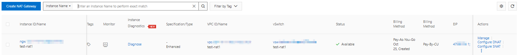
Step 2: Purchase an Internet NAT gateway
- Log on to the NAT Gateway console.
- On the Internet NAT Gateway page, click Create NAT Gateway.
When you create an Internet NAT gateway for the first time, click Create in the Notes on Creating Service-linked Roles section of the buy page to create a service-linked role. After the service-linked role is created, you can create Internet NAT gateways.
 For more information, see Service-linked roles.
 Set the following parameters.
Select a Region for the Internet NAT gateway.
ImportantThe Internet NAT gateway and the VPC created in Step 1 of this topic must be deployed in the same Region.
Select the VPC that you created in Step 1 of this topic.
Select the Associate vSwitch that you created in Step 1 of this topic.
Optional: Specify a Instance Name for the Internet NAT gateway.
Select Configure Later for the Access Mode parameter.
For more information, see Use the SNAT feature of an Internet NAT gateway to access the Internet.
Click Buy Now and complete the payment.
Step 3: Purchase an EIP
- Log on to the Elastic IP Address console .
On the Elastic IP Addresses page, click Create EIP.
Set the parameters of the EIP.
Select a Region and Zone for the EIP. Use the default settings for other parameters. For more information, see Apply for EIPs.
ImportantThe EIP and the VPC created in Step 1 of this topic must be deployed in the same Region and Zone.
Click Buy Now and complete the payment.
Record the IP address of the EIP.
If the purchase is successful, return to the Elastic IP Addresses page.
In the top navigation bar, select the region where the EIP is created.
Record the address of the IP Address column.
Step 4: Associate the EIP to the Internet NAT gateway
- Log on to the NAT Gateway console.
- In the top navigation bar, select the region where you want to create the NAT gateway.
On the Internet NAT Gateway page, find the Internet NAT gateway that you want to manage and click Associate Now in the EIP column.
NoteYou can also choose
 > Associate EIP in the Actions column of the instance.
In the dialog box, select Select Existing EIP, and then select the EIP you purchased in Step 3 of this topic.
NoteIf you purchase multiple EIP instances, repeat this step.
Click OK.
After you complete the preceding operations, the EIP is displayed in the EIP column.
Step 5: Configure SNAT entries to the Internet NAT gateway
- Log on to the NAT Gateway console.
- In the top navigation bar, select the region where you want to create the NAT gateway.
- On the Internet NAT Gateway page, find the NAT gateway that you want to manage and click Configure SNAT in the Actions column.
On the SNAT Management tab, click Create SNAT Entry.
Configure the following parameters.
NoteIf the SNAT entries for the VPC exist, you can click Edit in the Actions column to modify the parameter.
Select Specify VPC for the SNAT Entry parameter.
Select the EIP specified in Step 4 of this topic for the EIP parameter.
NoteSelect all purchased EIP instances that are associated with the Internet NAT gateway.
Disable EIP Affinity.
Click Create Now.
Wait until the Status of the SNAT entry is in Available.
Step 6: Configure alert rules for the EIP associated with the Internet NAT gateway
Log on to the Cloud Monitor console.
In the left-side navigation pane, choose .
On the Alert Rules page, click Create Alert Rule.
Configure the following parameters.
Parameter
Description
Product
Select Elastic IP Address.
Resource Range
Select Instances.
Associated Resources
Click Add Instance.
In the dialog box that appears, select a region and an instance to find the EIP associated in Step 4 of this topic.
Select the EIP.
NoteSelect all purchased EIP instances that are associated with the Internet NAT gateway.
Click OK.
Rule Description
Click Add Rule and select Combined Metrics.
In the Configure Rule Description panel, enter the Alert Rule.
In the Multi-metric Alert Condition section, configure alert rules for the OutboundRatelimitDropSpeed and InboundRatelimitDropSpeed.
NoteSet the metric to an average value greater than (>) 0 pps.
You can click Add Metric to add multiple-metric alert rules.
Select Generate alerts if one of the conditions is met (II) for the Relationship Between Metrics parameter.
Select the Alert Threshold Triggers based on your business requirements.
Click OK.
Alert Contact Group
Select the alert contact groups to which alert notifications are sent.
NoteFor more information, see Create an alert contact or alert contact group.
Other parameters
Configure other parameters based on your business requirements. For more information, see Create an alert rule.
Click OK.
Step 7: Add the EIP to the security settings of the database
Add the EIP associated in Step 4 of this topic to the security settings of the database, such as firewall policies, IP address whitelists, and security group rules.
Step 8: Create a DTS instance
Configure the following parameters to the Source Database and Destination Database parameters of a DTS instance, and complete subsequent configurations based on your business requirements.
For more information, see Overview of data synchronization scenarios, Overview of data migration scenarios, Overview of change tracking scenarios, or Configure a data verification task.
Select Database Type based on your business requirements.
Select Access Method as the Express Connect, VPN Gateway, or Smart Access Gateway.
Select Instance Region as the region where the VPC is deployed that you create in Step 1 of this topic.
Select Connected VPC as the VPC you create in Step 1 of this topic.
Select Domain Name or IP as the domain name or IP address of the database server.