Get Fortinet FortiGate on Alibaba Cloud by visiting our Marketplace:
Fortinet FortiGate (PAYG) Next-Generation Firewall (4 vCPUs)
Fortinet FortiGate (PAYG) Next-Generation Firewall (8 vCPUs)
In this 3-part article series, we will show you in detail the steps for deploying and configuring Fortinet FortiGate (FGT) A-P High Availability (HA) on Alibaba Cloud between availability zones (AZ).
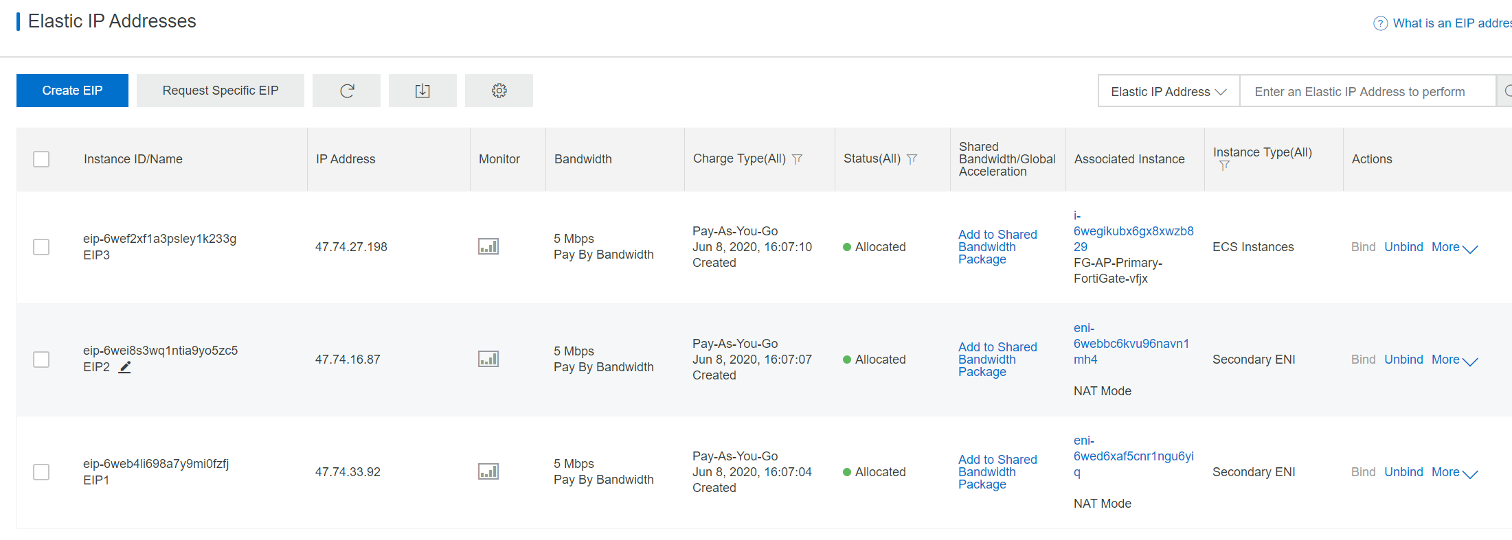
After starting the instance, log in via EIP1 IP address to FGT1, and EIP2 IP address to FGT2. Change your password by following the instructions. By default, HTTPS port 443 is accessible.
Install the license.

Upload your license file (FGVM1VTM20000859.lic), which was downloaded from support.fortinet.com. After rebooting, you will be able to login into FGT1 and FGT2.
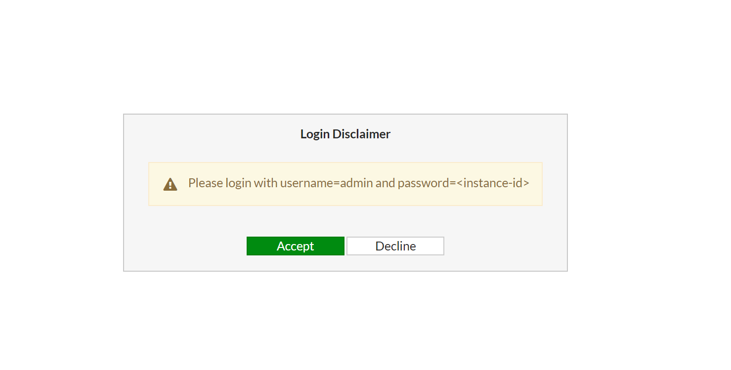
You will be asked to input the default password (which is instanceid) and asked to change the password. Then, you will be asked to import the license file you previously downloaded from support.fortinet.com. After that, Fortigate will be rebooted. Please note that the license may take up to 30 minutes to be active, so be patient for license to become active.
You can configure Fortigate by following the cookbook. Basically you will have to configure the interface address and routing table.
The interface IP address has to match ENI IP addresses and the port number should match the ENI numbers.
Configure the default route for both Fortigate; you can get the gateway IP address from port1 DHCP setup.
On FGT2, configure a static route to 10.0.12.0/24 with exit port2 is required. This is needed after the switchover happens. Web-a server in zone-A will talk to FGT2 in zone B. Configure this route will let FGT2 send traffic back to web-a in ZoneA directly via port2.
If you do not have any workload in zone-B internal-B subnet. You do not need to configure 10.0.22.0/24 on FGT1 but on FGT2. We need to config 10.0.12.0/24 as web-A is on this subnet.


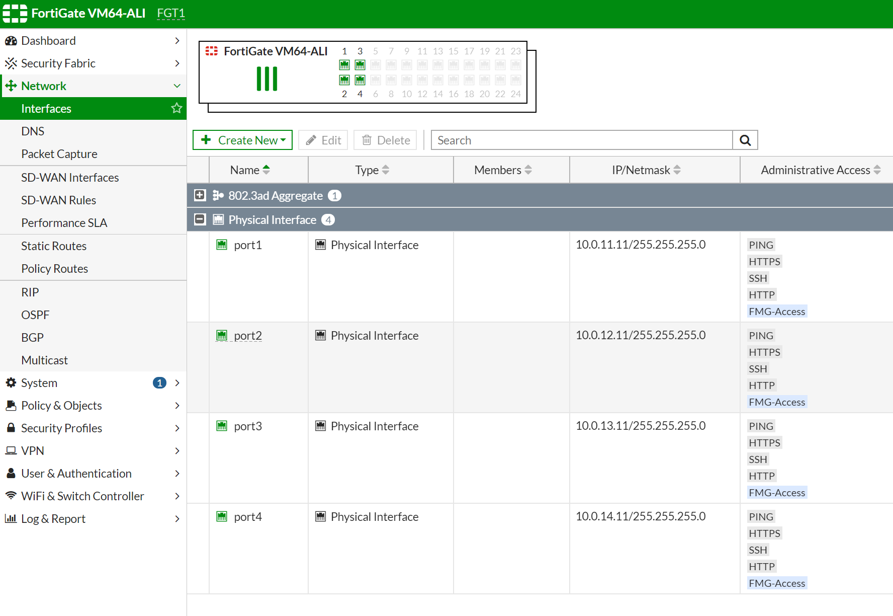
By default, all interface are using DHCP to get ip address from vRouter, port1 is instance-1 primary interface which is default ENI, port2 is instance-1 is first secondary ENI and so on.
Configure static IP address instead DHCP, do same for both Fortigate instances.
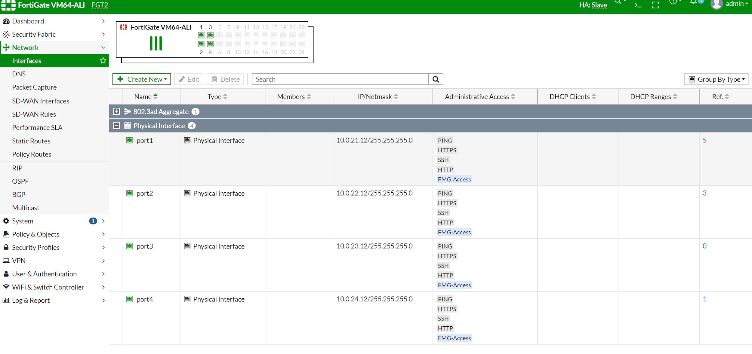
After configuring the interface IP address and static route, you shall see configuration on two Fortigate like this.
FGT1 (interface) # show
config system interface
   edit "port1"
       set vdom "root"
       set ip 10.0.11.11 255.255.255.0
       set allowaccess ping https ssh http fgfm
       set type physical
       set snmp-index 1
   next
   edit "port2"
       set vdom "root"
       set ip 10.0.12.11 255.255.255.0
       set allowaccess ping https ssh http fgfm
       set type physical
       set snmp-index 2
   next
   edit "port3"
       set ip 10.0.13.11 255.255.255.0
       set allowaccess ping https ssh http fgfm
       set type physical
       set snmp-index 3
   next
   edit "port4"
       set ip 10.0.14.11 255.255.255.0
       set allowaccess ping https ssh http fgfm
       set type physical
       set snmp-index 4
   next
   edit "ssl.root"
       set vdom "root"
       set type tunnel
       set alias "SSL VPN interface"
       set snmp-index 5
   next
   edit "fortilink"
       set vdom "root"
       set fortilink enable
       set ip 169.254.1.1 255.255.255.0
       set allowaccess ping fabric
       set type aggregate
       set lldp-reception enable
       set lldp-transmission enable
       set snmp-index 6
   next
end

FGT1 (interface) #
FGT2 (static) # show
config router static
edit 1
set gateway 10.0.21.253
set device "port1"
next
edit 2
set dst 10.0.12.0 255.255.255.0
set gateway 10.0.22.253
set device "port2"
nextFGT2 # config system interface
FGT2 (interface) # show
config system interface
edit "port1"
set vdom "root"
set ip 10.0.21.12 255.255.255.0
set allowaccess ping https ssh http fgfm
set type physical
set snmp-index 1
next
edit "port2"
set vdom "root"
set ip 10.0.22.12 255.255.255.0
set allowaccess ping https ssh http fgfm
set type physical
set snmp-index 2
next
edit "port3"
set ip 10.0.23.12 255.255.255.0
set allowaccess ping https ssh http fgfm
set type physical
set snmp-index 3
next
edit "port4"
set ip 10.0.24.12 255.255.255.0
set allowaccess ping https ssh http fgfm
set type physical
set snmp-index 4
next
edit "ssl.root"
set vdom "root"
set type tunnel
set alias "SSL VPN interface"
set snmp-index 5
Next
edit "fortilink"
set vdom "root"
set fortilink enable
set ip 169.254.1.1 255.255.255.0
set allowaccess ping fabric
set type aggregate
set lldp-reception enable
set lldp-transmission enable
set snmp-index 6
next
endFGT2 # config route static
FGT2 (static) # show
config router static
   edit 1
       set gateway 10.0.21.253
       set device "port1"
   next
   edit 2
       set dst 10.0.12.0 255.255.255.0
       set gateway 10.0.22.253
       set device "port2"
   next
endThe next step is to configure HA setup.
FGT1 #  config system ha

FGT1 (ha) # show
config system ha
   set group-name "fgtha2"
   set mode a-p
   set hbdev "port3" 50
   set session-pickup enable
   set ha-mgmt-status enable
   config ha-mgmt-interfaces
       edit 1
           set interface "port4"
           set gateway 10.0.14.253
       next
   end
   set override disable
   set priority 100
   set monitor "port1"
   set unicast-hb enable
   set unicast-hb-peerip 10.0.23.12
end
FGT2 # config system ha
FGT2 (ha) # show
config system ha
set group-name "fgtha2"
set mode a-p
set hbdev "port3" 50
set session-pickup enable
set ha-mgmt-status enable
config ha-mgmt-interfaces
edit 1
set interface "port4"
set gateway 10.0.24.253
next
end
set override disable
set priority 50
set monitor "port1"
set unicast-hb enable
set unicast-hb-peerip 10.0.13.11
end
FGT2 (ha) # After configuring HA, you should see the two Fortigate now in Cluster mode. In Cluster mode, both Fortigates will be in-sync. FGT1 has a higher priority so it will become master and FGT2 will become slave.


Take a look again at the routing table on FGT2. You can see the routing table is changed to 10.0.11.253. This means the configuration of the static route is also synced with FGT1. This is not expected, as FGT2 default routing table shall point to 10.0.21.253. We can configure to exclude sync static configuration. After that, static routing will NOT be synced.
FGT1 # show system vdom-exception
config system vdom-exception
   edit 1
       set object router.static
   next
end

FGT1 # execute ha manage 0 admin
admin@10.0.23.12's password:
FGT2 # show system vdom-exception
config system vdom-exception
   edit 1
       set object router.static
   next
endNote that when you cannot ping HA interface address from the root vdom (which is the default administrator domain), HA port is automatically moved to another administrator domain called (vsys_ha) domain. In that domain, you will be able to ping HA interface from FGT1 to FGT2, you can use "execute enter root" go back to root domain.
FGT1 # execute enter vsys_ha
current vdom=vsys_ha:2

FGT1 # execute ping 10.0.23.12
PING 10.0.23.12 (10.0.23.12): 56 data bytes
64 bytes from 10.0.23.12: icmp_seq=0 ttl=255 time=1.7 ms

--- 10.0.23.12 ping statistics ---
1 packets transmitted, 1 packets received, 0% packet loss
round-trip min/avg/max = 1.7/1.7/1.7 ms
Next step we will create a sample VM to test ingress and egress traffic goes through firewall Fortigate.
We will launch a linux machine in vswitch internal-A. This switch should be able to reach the internet through fortigate, and we also configure a web service in this VM. Allow public access to this VM by configuring the policy on fortigate from vm to access the internet. We need to configure a policy on fortigate to allow this traffic and do a SNAT for ingress to this VM. We need to configure a policy on fortigate for DNAT and configure a VIP for this vm.
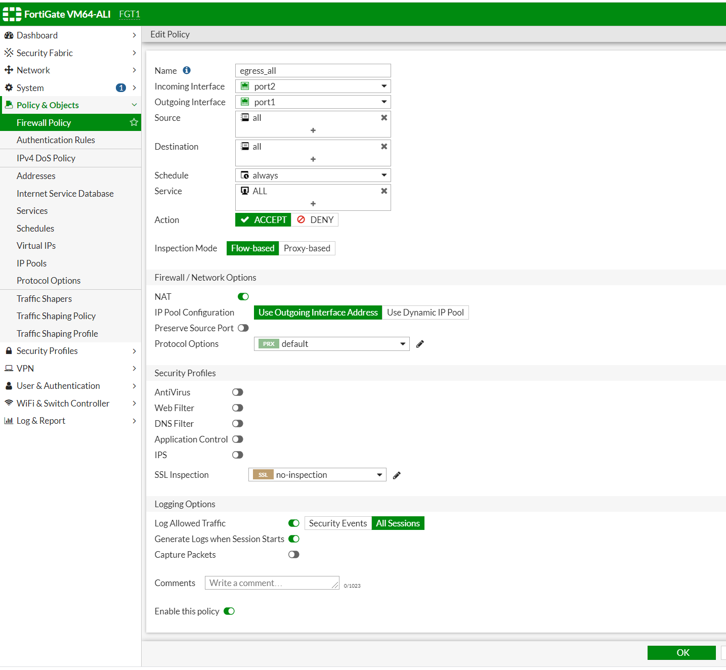
The traffic comes from port2 (attached to vswithinternal-A) and exits from port1 (attached to vswitch external-A). Port 1 is also the interface for the FGT-1 default route. We have to enable NAT. When traffic leaves port 1, the source IP of the VM will become the port1 interface's IP address which is 10.0.11.11.
For Ingress traffic, we need to create a VIP to represent VM and then create DIP to that VIP.
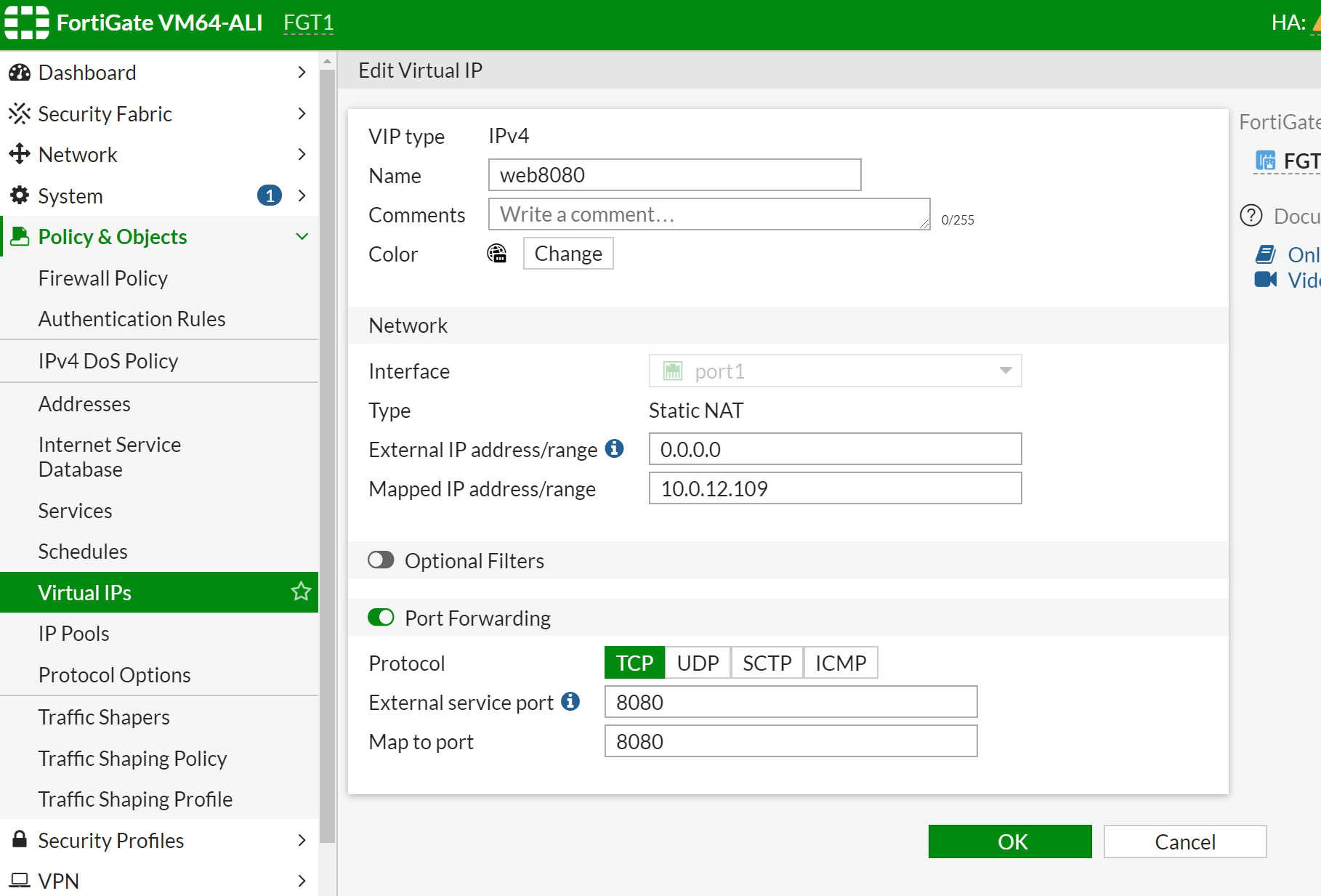
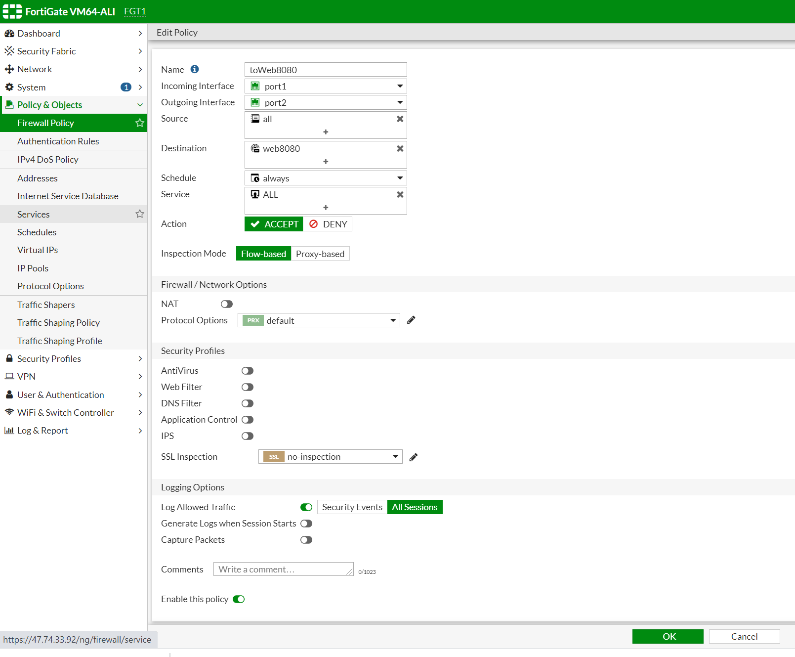
Incoming traffic will come from port 1 (external-a switch), and reach port 2 (internal-a switch). If the destination is web8080, Fortigate will do a Destination NAT. Replace the IP address of fortigate EIP3 (which is associated with master fortigate) to the VIP of VM which is 10.0.12.x).
Do not enable NAT as here we do not need SNAT.
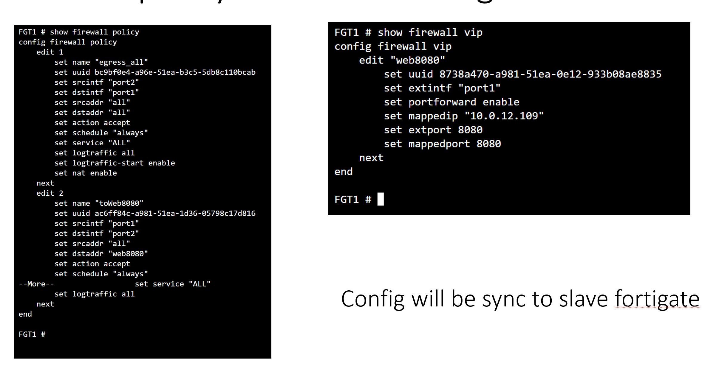
You can also configure vip and firewall policy in cli as shown below.
The traffic between vswitch in different zones has to go through default router via port 1.
After switching over, the incoming traffic from the internet will arrive port 1 on FGT-2, then it will then do A DNAT, translated to DIP address of web-a VM which is 10.0.11.209. Then, it will find a routing table to reach that address, which is in Zone-A. So it will again go back to port 1 to vrouter. vrouter will take that packet to web-A vm in zone-A. Therefore, we have to configure a policy for incoming traffic that arrive on port 1 and exist on port 1.
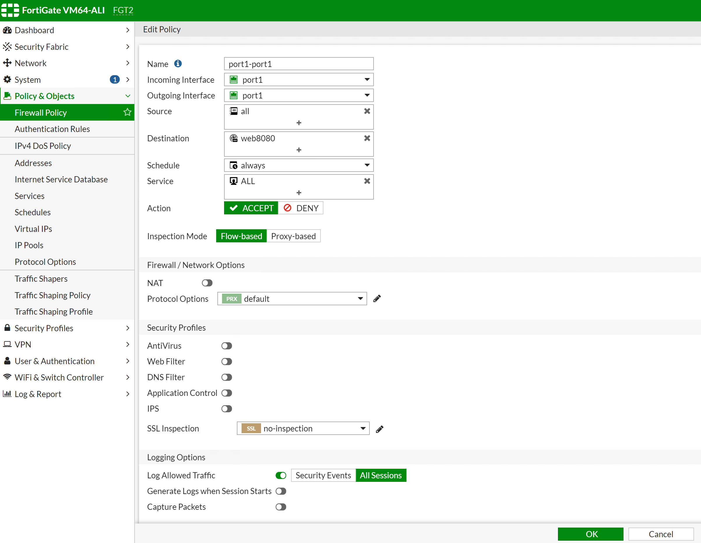
FGT2 # config firewall policy

FGT2 (policy) # edit 3

FGT2 (3) # show
config firewall policy
   edit 3
       set name "port1-port1"
       set uuid 4bb3372a-adec-51ea-2fb1-7e5bbbe37e5b
       set srcintf "port1"
       set dstintf "port1"
       set srcaddr "all"
       set dstaddr "web8080"
       set action accept
       set schedule "always"
       set service "ALL"
       set logtraffic all
   next
end

FGT2 (3) #
If you turn on packet trace for HTTP client that access web-a 8080, you will see below logs:

Wait until the functions between master and slave become in-sync. Once complete, you have done all the configuration for Fortigate.
In the last article, we'll be showing you how you can verify your setup and troubleshoot any issues that may arise
https://github.com/yagosys/fortigate_aliyun/tree/master/AP-CrossZone
Get Fortinet FortiGate on Alibaba Cloud by visiting our Marketplace:
Fortinet FortiGate (PAYG) Next-Generation Firewall (4 vCPUs)
Fortinet FortiGate (PAYG) Next-Generation Firewall (8 vCPUs)

21 posts | 12 followers
FollowMarketplace - August 17, 2020
Marketplace - August 18, 2020
Marketplace - February 21, 2019
Marketplace - September 17, 2021
Alibaba Cloud Community - August 18, 2022
ApsaraDB - March 4, 2021

21 posts | 12 followers
Follow WAF(Web Application Firewall)
A cloud firewall service utilizing big data capabilities to protect against web-based attacks
Learn More Cloud Firewall
Provides traffic control and security protection for the Internet, virtual private cloud (VPCs), and hosts in VPCs
Learn More Web Hosting Solution
Explore Web Hosting solutions that can power your personal website or empower your online business.
Learn More Web App Service
Web App Service allows you to deploy, scale, adjust, and monitor applications in an easy, efficient, secure, and flexible manner.
Learn MoreMore Posts by Marketplace