By Zhang Ronghua (Ronghua)

This article shares the architecture methodology of Ronghua, a senior technical expert at Alibaba. This methodology contains the detailed architecture derivation logic, hoping to help you do the architecture work well from all granularity and levels in your work.
The process can be described as follows: the requirements analysis, architecture implementation, and if new requirements emerge, you need to modify the architecture, which may happen many times. Finally, it means the need for re-design. This process is a round-robin process, and some products will be pushed over again every year.
What causes this process? One of the reasons is that each iteration does not use the correct architecture derivation method to carry out the iteration, just as adding a floor on a crooked stairs, which will eventually collapse. However, this is not the only reason, and other reasons will be explained in the rest of the article.
Most of us have experienced this; the reality is sad but it is fairly common. A commonly proposed solution to solve this problem is to use the correct method in each iteration. Or is it? An important reason for using the correct method is the architecture. Just like a building, the more problematic the architecture design is, the greater the probability that this building will be rebuilt.
What is the correct method here? In this article, we will elaborate a set of architecture methodology, which includes the detailed architecture derivation logic, helping us do the architecture work well from all granularity and levels in our work.
In the following sections, we will focus on how to solve these problems from the bottom-up and top-down architectural thinking. However, before that, first, let's talk about what "architecture" is.
About 11 years ago, I worked on the advertising platform for Tudou and also did something related to the video Content Delivery Network (CDN). At that time, I did a service and its architecture was lighttpd + squid + tomcat. This architecture separated the static resources to httpd, used squid for get requests, used HTTP POST requests for intelligent routing, and let tomcat provide services. At that time, I considered this was "the" architecture. Later, after doing the basic establishment work related to video CDN and I felt that I was doing the architecture. At that time, no one told us what the architecture was and I didn't know that I didn't know the architecture.
I went to do middleware for several years, including high-performance Remote Procedure Call (RPC) and Java Specification Request 170 (JSR-170). Then, I felt that I was also working on the architecture. At that time, no predecessors told me what architecture was. At that time, I didn't have a systematic understanding of architecture. I did it with my feelings. I didn't know that I didn't know it.
Finally, I came to Alibaba to do application development and architecture. I found that business development also included various methodologies. However, the modeling related materials I had seen before did little help to my work on middleware and other infrastructure. Instead, they played a huge role in the business technology field. I also found that the architecture closer to the user becomes more and more important as the enterprise grows bigger. It is at that moment when I realized that I didn't really know what architecture was about.
Now that I knew that I didn't know what architecture was, I have to pursue it. I used to discuss about architecture with many business developers. Without talking about the perspectives of infrastructure architecture and physical architecture (these perspectives need a long time to explain), I have selected the application logical architecture and try to describe it from several perspectives:
1) From the perspective of the general principle of the architecture: Make the architecture as simple as possible, but not too simple. You need to make it as simple as possible to facilitate expansion and maintenance, but not too simple that it causes omissions.
2) From the perspective of the purpose of the architecture: It aims to solve the problems of the past, of the present and of the future. These problems include technical and business problems.
3) From the perspective of the two-dimensional form: The architecture is related to something vertical and horizontal. The horizontal definition means layering, vertical definition means partitioning and there are abstract things to do.
4) From the perspective of the three-dimensional form: The architecture is three-dimensional, with horizontal and vertical problems on the x-axis and y-axis, and granularity problems on the z-axis.
5) From the perspective of timeline: The architecture changes constantly with the development of the business.
I have described the architecture from the preceding perspectives. However, these descriptions are personal insights, from a certain perspective to view the architecture. In my heart, I feel I have not refined it enough. The summary in practice must be combined with the knowledge of the industry. I must learn the system that the predecessors have summarized.

I think this top-level abstraction is in place. According to this definition, in the architecture, we need:
The definition of this architecture is very concise and practical. Such content can be implied in the operation of a country as small as a toy.
However, this is an architecture defined in a broad sense. After some summary, I think there will be more refined architecture categories at different levels in our daily work.
At work, I met people in different positions to describe the structure from different perspectives, but we rarely reached a consensus. At first, I didn't know why we couldn't reach a consensus. After a period of confusion and in-depth and careful thinking, I found that most of the architectures described are not from the same category. Therefore, I try to categorize architectures from the following perspectives. The categories are to help us focus on which architecture we are discussing in different scenarios and conversations with different people, in order to improve communication efficiency and reach a consensus as soon as possible. At present, this division has basically been accepted by our team.
It should be noted that, the following architectures all conform to the definition of the general architecture explained in the previous section: Modules (components) + Relationships + Constraints & Guidelines.
This is a product manager's favorite architecture. Generally speaking, when we talk about what features we have, the feature oriented architecture describes what we can do, and the audience are generally those who use the product. When designing software, we should produce the application logical architecture and application physical architecture, instead of producing the feature oriented architecture. But once we want to publicize our products, such as the use of our interfaces and how to use them, we should talk about the feature oriented architecture at this time.
It is used to analyze the business. It refers to the respective business modules and their capabilities. This diagram helps us analyze and understand the business requirements. It also helps the product manager to analyze the business. Therefore, the business conceptual architecture and business conceptual model are both used in the analysis phase.
This architecture includes software design itself, modules, granularity, responsibilities, reuse, and so on. When explaining the software design, we use this architecture diagram, which is derived from the system model and business conceptual architecture. Therefore, the system model and application logical architecture are both used in the software design phase.
This application physical (deployment) architecture diagram derives from the application logical architecture. In the derivation, the focus is on how to implement the logical architecture. For example, it focuses on what kind of microservice container to use, whether the module of the logical architecture should be package or application, or a group of applications, and whether it needs to be deployed across data centers or even across countries. In addition, topics such as stability, performance, and cost must be considered.
It is related to the selection of middleware, storage, monitoring, alarm, etc.
In the daily architecture discussions, some often talk about the capabilities and responsibilities of the architecture. Then, what is the difference between its capabilities and responsibilities? After dealing with the product personnel, I found that many of the product personnel are talking about capabilities. Later, the technical personnel began to talk about capabilities, and usually our personnel of the architecture are talking about responsibilities. What is the difference between the two? Let me talk about my opinions:
1. Capabilities (Capabilities of Product Feature Modules)
Capabilities refer to what a product can do. For example, the mid-end itself is a product. For personnel who use mid-end, we should talk about the capabilities of mid-end (in fact, the capabilities of the middle end product). Therefore, the talking of capabilities is for architecture users or others who want to know.
2. Responsibilities (Responsibilities of Each Module in the Logical Architecture)
Responsibilities refer to the responsibilities of the modules within the architecture. They are used to guide the development. For example, the mid-end research and development personnel should talk about the responsibilities, dependencies, and constraints of the architecture. Therefore, responsibilities are introduced to research and development engineers, architects and managers. In general, responsibilities are introduced to the architecture implementers.
In short, capabilities refer to the capabilities of the product, and responsibilities refer to the responsibilities within the architecture. If the architecture itself is also a product that needs to be output to the outside world (for example, the mid-end or some other technical frameworks serve as products), we should talk about the capabilities of this technical product. (At this time, technical personnel will begin to talk about capabilities.) So when we discuss a problem, if some people are talking about product capabilities and some people are talking about internal responsibilities, then obviously they are talking about different topics. Please pay attention to distinguishing this situation. The difference is as good as a mile. The dialogue of the deaf needs to be avoided.
For example, Module A and Module B have different responsibilities but depend on the same second-party library. Then we cannot say that a certain duty is in this second-party library. As an independent technology product, this second-party library provides some capabilities. However, it is Module A or Module B that performs duties.
As described in the architecture categories section, some architectures are irrelevant to specific businesses whereas some architectures are closely related to specific businesses. For example, an application logical architecture is closely related to businesses and comes from the abstraction of the business. We can even say that it is the first output in the technical architecture design of the business line.
Since it is the first output, we must consider the three types of topics that should be included in the application logical architecture:
The vast majority of architectural problems can be summarized into these three types. What are these topics involved? This is what the next part is going to introduce. The design of the application logical architecture is not based on your personal inspiration, but is derived through a scientific method system.
In general, there are two methods to produce an architecture: One is a top-down derivation, and the other is a bottom-up derivation. Moreover, the two methods are often combined to produce the most appropriate results. The business personnel are most exposed to the bottom-up derivation, which is also the architecture derivation method that this article focuses on.
The key for top-down derivation is the problem definition. If the problem is not accurately defined, this derivation cannot get the correct result. If the problem is accurately defined, how does the top-down derivation work?
Our developers in the business line must deal with many requirements every day. Where do these requirements come from? They basically come from three sources:
After these detailed requirements from the product owners come, how do we deal with them? We first discuss the rationality of the product solution with the product owners. On the basis of the reasonable product solution, we begin to identify the use cases and start a series of measures in the field of software engineering. The following diagram shows the process:
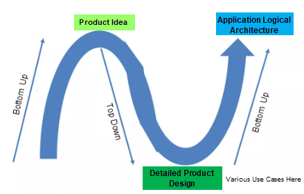
The bottom-up logical architecture is the curve on the rightmost side.
This is basically what the following article is about to focus on: how to derive the application logical architecture from the bottom-up method, which is an abstraction and architecture building process.
Starting from the introduction of the overall methodology, we adopt the structure of the total score. The following figure shows the bottom-up derivation path of the application logical architecture. This derivation path is orderly and each step contains a lot of operation skills. Only by doing well in the first step can we get the correct result in the later step.
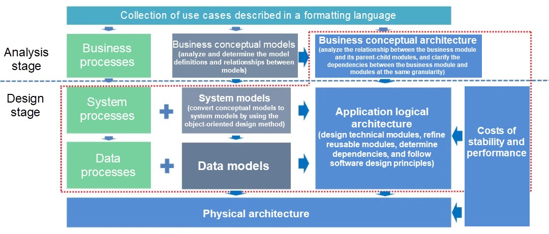
The following are the key points in this figure:
1) The software development falls into two phases:
2) The arrow in the figure illustrates the main thinking path of architecture derivation. It also shows that building the architecture does not need to be based on your inspiration but is derived on the strict logic.
The strict logic is basically a bottom-up derivation process. The underlying model is deduced by the modeling method, and each module in the logical architecture is deduced by the inductive method. So:
Let's leave them in suspense and talk about them later.
Both deduction and induction are part of abstraction and need materials. The materials here are our understanding of requirements, business, and technology. Without materials, no result can be obtained even if we have mastered methodology.
Most of the business materials come from areas where you need to solve issues. For example, if we are in the e-commerce field, we need to gather more business knowledge in this field. If we are in the data field, we naturally need to gather more knowledge about data services and the technical knowledge we mentioned earlier.
The technical materials require us to continuously study in the technical field, constantly expand the knowledge boundaries and increase the knowledge in depth and breadth. Therefore, it is absolutely necessary for architects to continuously improve their understanding of computer science and technology.
A pre-condition of top-down derivation is that you need to know what a pig looks like, what the original architecture looks like and what problems it can solve. If you don't know what a pig looks like, then you can't judge whether a pig is suitable as a pet. You need to have a certain understanding and experience of the business field (including: the customers' problems and pain points, the way to analyze them, and the current architecture solution, the way that the current architecture solution solves these problems and the better way that the future architecture solution solves these problems).
However, the bottom-up derivation does not have this problem, because it is to look at the pig to do the derivation. Therefore, you know the details of the pig, know how to deduce or induce the characteristics of this detail and finally draw a conclusion.
When we are not familiar with a large business, it is extremely difficult to perform the top-down architecture derivation. The issue defined without understanding the business or technical situation may not be a correctly defined issue, which easily gives the impression of misdirection.
At this time, the architecture for rapid implementation without prior knowledge has to be derived from the bottom-up. Get familiar with the business in the bottom-up process.
However, if we purely derive the architecture from the bottom-up at work, it cannot help us to make a forward-looking layout of technology. At this time, the growth of architects will encounter bottlenecks, so we need to use the top-down architecture derivation method.
In summary, both bottom-up and top-down are skills that architects need to master.
I have shared this part with personnel in International Core Business Unit (ICBU), Taobao Village, Onetouch, Cainiao and AliExpress (AE). Especially in AE, Onetouch and Cainiao, relevant personnel all came up with the difficult problems that had confused them for a long time at that time. We used this bottom-up method together and soon analyzed the business conceptual model. We briefly divided the modules to form the outline of the business conceptual architecture. After a lot of practices, the effect is very obvious.
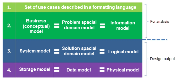
Here, I will gather some common concepts to help unify the concepts:
1) The business conceptual model, issue spatial domain model, and information model mean the same thing. Entities at this layer are called conceptual entities. This part of content is used for demand and business analysis. The software implementation does not need to be considered at all when discussing the business conceptual model. This is an analysis process, so even if no software research and development is done, there should be a similar analysis process for other research and development.
2) The system model, solution spatial domain model, and logical model mean the same thing. Entities at this layer are called system entities, or logical entities, which are all types. These entities are used in software design and software research and development.
3) The storage model, data model and physical model also mean the same here. Entities at this layer are called data entities or physical entities, which are also used in software design.
These three layers are actually looking at the issues from three perspectives. They are the top-down conversion relationship. The two words that should be paid special attention to here are: logical and sequential derivation.
These different layers of models are the foundation of the application logical architecture.
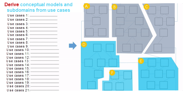
Derive the business conceptual models based on use case sets.
Derive the associations between the business conceptual models based on the verbs and quantifiers in the use cases.
Induce subdomains within specific boundaries based on the responsibilities of the models.
Important. Important. Important. Here if the business conceptual models are not analyzed correctly, it is not easy to figure out the following part. This analysis part is the basis of the software logical architecture design.
This part requires us to understand the business and, more importantly, to master the rigorous methodology of problem spatial modeling, so that we can derive a reasonable model. The whole process is very rigorous and logical.
On the business unit (BU) sharing meetings, I can successfully and quickly help personnel sort out the models that they hadn't worked out for one or two months because they had a good understanding of the business (because I had no idea about the business before the discussion) and I provided this methodology (implied in my questioning method). Therefore, both the business understanding and the methodology are indispensable.
After the model is generated, we need to induce the model.
What is induction?
Induction is to combine all results and ideas into a kind of thinking concept. Or let a model belong to an existing thinking concept. And the responsibilities of these models or modules cannot exceed the boundaries of this high-level thinking concept.
Why do we need the induction method?
In fact, it is to ensure that similar responsibility models gather together to achieve high cohesion of responsibilities, and define the boundaries of the two subdomains, thus ensuring the low coupling between modules.
The induction of business conceptual models helps to judge the high cohesion and low coupling during business requirement analysis. To classify system models is also helpful for the high cohesion and low coupling of modules in the application logical architecture. However, the application logical architecture not only supports the high cohesion and low coupling, but also provides other methods for single responsibility. These will be described in the following part.
The following are some examples of how to judge a business conceptual model and a business conceptual architecture:
1) Induce the Thinking Concept by the Definition of Nouns
If multiple models revolve around a noun, we tend to extract that noun. At the time of product design, basically we can already get a rough division of business modules, but this rough division is not necessarily reasonable:
2) Induce by the Cohesive Measurement Formula

In the business model diagram, the value obtained by dividing the number of models and model connections (lines are the connecting lines of the models and the models) by the combing of the models is relatively large, so we can see it as cohesion. These lines are relatively close and we tend to put them into one module. When the lines are not so close, we tend to place them in different modules. The cohesion value is obtained by dividing the number of lines by the number of models. Then we observe whether the cohesion is high or low by this value. After the induction is completed in this way, then we use the measurement formula to measure the cohesion and coupling of each module.
3) Other Induction Methods
If we have divided the basic modules and find that there are still some models that are not sure which module should be put into , we can also use the creator principle and the information expert principle to determine which module these modules should be classified to.
For example, when performing system modeling on storage systems, the relationship between tables and fields is a one-to-n relationship in the business conceptual model. It is a combination relationship and strong lifecycle dependence in the system model. However, before we discuss the application logical architecture, we are only deriving the business conceptual architecture. At this time, it is obviously inappropriate to put the field in another module based on the creator principle.
When we are not sure which module to put the field model into, we can look at who created the field model.
According to this principle, it is obvious that the table creates a field. Without the table object, there is no field object. According to this principle, we tend to put the field model into the module where the table is located.
Key point: Without the reasonable and correct deduction at the bottom, it is difficult to get a reasonable result even if the upper layer induction is well mastered.
Let's take a look at the effect diagram after induction:
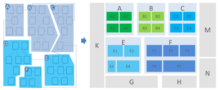
A1, A2, A3, A4 and the like are diagrams, indicating that there are submodules in Module A. Of course, we actually derive submodules first, and then induce the submodules at a high level to form a parent module.
The parent module level is induced to form the grandfather module, or form the great-grandfather module upwards. As the granularity of a module becomes larger, the corresponding organization becomes larger and the cross-team communication becomes more, so drawing a clear boundary becomes more demanding.
In addition to the business model, we also need to summarize and define the business process. We mainly need to define the boundaries and exception branches. In particular, exception branches are very important. In many business solution designs, the considerations of exception branches are not repeated, which requires engineers to challenge the business solutions to clarify the exception branches in various processes in the business solutions.
There are two common derivation methods in our work. One is top-down derivation and the other is bottom-up derivation. Obviously, the two derivation methods are different. Careful readers will find that the methods we just mentioned about the issue spatial domain mode and boundary analysis are the bottom-up deduction and induction methods.
The previous part describes the business analysis phase, which is also involved in the problem spatial modeling and the sorting of problem spatial business conceptual architecture. The business analysis phase is not related to software. However, in this article, it is a prerequisite for software design. For those who have not mastered this point, please read the previous part carefully.
Next, let's talk about the application logical architecture that we need to produce in the software design phase.
Let's review the characteristics of the logical architecture mentioned at the beginning:
Please be sure to distinguish it from the feature oriented architecture because their audiences and purposes are different.
In the diagram at the beginning, we mentioned that the application logical architecture comes from the system models, data models, business conceptual architecture, and their processes, as shown in the following figure.

The following sections describe the generation of a logical architecture from three perspectives:
I saw that many diagrams drew by others did not distinguish between the call flow and the data flow. These diagrams often caused misunderstanding, reduced communication efficiency, and even failed to accurately explain the problem. Therefore, when drawing, your attention must be paid to distinguish the call flow from the data flow.
Then, derive the application architecture (logical architecture) based on the business conceptual architecture, system model, and process. Let's look at the animation diagram of a simple logical architecture:
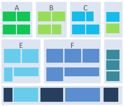
From this diagram, we can see how the application logical architecture is constructed step by step. The entire process has the following key points:
1) Deduce the application logical architecture based on the business conceptual architecture.
2) Improve the application logical architecture based on the processes and system models.
3) The problem of horizontal refining module is to realize the business module, what non-business module support is needed, such as monitoring, alarm, configuration, etc. This part is often reusable. In the above animation, it can be understood as the part moving to the rightmost. Of course, it can be moved to the left, but it is not reflected in the animation.
4) The problem of vertical refining module is whether modules with similar responsibilities can be refined into reusable content in terms of technical implementation, and the result may be as follows:
5) Some other modules are used to support performance and stability. They are not extracted from business conceptual models, such as the deep blue modules in the diagram.
The final logical architecture is a hierarchical and sharded logical architecture. Let's go through the process step by step.
After the business conceptual architecture diagram is generated, basically, the preliminary model of the logical architecture appears. Therefore, the first step is to move the business architecture directly to the application logical architecture. There is no need to elaborate here.
In particular, the top-level coarse-grained business architecture is derived from the top-down decomposition, and the other is derived from the bottom-up deduction and induction. The top-down approach tests personnel's ability to understand the business in particular. If you do not have a thorough understanding of the business, it is difficult to generate a reasonable and coarse-grained business conceptual architecture.
After the business conceptual architecture is produced, the skeleton of the logical architecture is initially built, and then the content is added to this architecture. The first step is to divide modules according to the processes.
To sum up, the method here is to create a system sequence diagram based on the business processes first. Then, you need to summarize the modules based on the sequence diagram to obtain modules with larger granularity.
This is a fine-grained case of dividing modules according to processes. This method is also applicable to processes with larger granularity, depending on the granularity of work.
Deduction through processes is an essential part of our daily work. In particular, when the processes in many scenarios have business commonalities, we can consider refining these business commonalities to improve the efficiency of research and development.
In addition to the process induction, we can also induce the system models. We know that business conceptual models can be directly converted to system models, but system models are not merely business-domain-related models. For example, the query model is a common model, this is very common and a pillar in On-Line Transaction Processing (OLTP) scenarios. A very common module is the SQL parser module. The following figure shows the main processes and corresponding models of SQL in the Spark system. We can basically sort out the modules based on this model:

According to this process, what do we find? Now, we have found that Spark divides modules like this. The modules here have already been implemented into packages. :
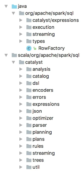
Therefore, it is very important to derive modules based on the system process converted from the business process.
In addition, it should be emphasized that processes and modules are of granularity. Only when process nodes of the same granularity are put together can it be easier to derive reasonable architecture modules. For more information about what is the same granularity, see The Minto Pyramid Principle.
The process granularity is very important. Please pay attention to it.
The previous section describes the architecture derivation from the business perspective. Next, we will elaborate the derivation of these non-functional modules from the perspective of computer science and technology. Here, let's take the performance as an example.
In some data analysis products, performance monitoring and report display is a very important scenario. In this scenario, the amount of data is relatively large. To reduce RT, we have to precompute the data through Extract-Transform-Load (ETL) and scrub the original large tables into small tables after aggregation to speed up the query. The disadvantage of this is that every time the report is modified, you need to run the relevant ETL logic. It takes a long time and high labor costs, and requires high performance.
To convert the long time and labor costs into low costs and high performance, we need to convert manual operations into automatic operations to remove the ETL process.
The first option is to store the data of a large table to another high-performance query engine that supports big data. This greatly reduces ETL operations. However, this causes a problem. It takes a long time to import data from MaxCompute to a Relational Online Analytical Processing (ROLAP) query engine, when there is a large amount of data. In addition, each query needs a lot of scans in massive data, but in fact, the amount of data obtained is not large. The RT of such a query needs to be sub-second.
The second option is to automatically determine the results that the user needs to query according to the definition of the report, and calculate the query results in advance. Then, only a small amount of these precomputed results are imported into the ROLAP engine. For more information, see Kylin, an Apache open source project. In the report scenario, the query RT is reduced to be hundred-millisecond.
Obviously, we need to implement the second option. At this time, we must add a module without increasing the business features. In our product, we call it the intelligent cube because we introduce machine learning algorithm to predict the construction of the cube, without or only a very small amount of human participation.
Some of the logical architecture is derived from the business conceptual architecture, some is derived from the system process, and some is generated due to the performance and cost requirements.
Note: Theoretically, the dependencies between modules need to be pointed out in the logical architecture, but this is not particularly beautiful. Therefore, the relationship between modules is roughly described according to the positions of top, bottom, left and right.
These two options basically show that the modules derived from performance, cost, and stability are also important components of the logic architecture.
However, this can only solve the RT problem for one scenario at one time. Although the cube has an internal system, solving the RT problem in this way is also a part of the bottom-up construction for the entire architecture. In the next article, we will elaborate on the same case, but the idea is to build a systematic architecture for the performance domain through the top-down method. The same thing, with different ideas to do, is not the same for the overall goal. The two methods are complementary, and no one is indispensable.
How do such modules come from?
It seems that we all know that there are many similar pure technology-related modules in the system, but how are these modules designed internally?
Generally, the following methods can help us with the internal design of these modules:
1) Check whether open-source technology products in the industry have similar functions. For example, Kylin is currently available for precomputing and Transwarp and other big data companies have their own cube precomputing products.
2) Consult the relevant papers in the industry. For example, in the field of precomputing, there are different papers at different stages of computer development, most of which are available online. Continuously studying these papers will be helpful to our work.
3) Pay more attention to the outstanding people in the industry. See what they are thinking, what they say, and participate in relevant meetings.
4) Derive it through the logical and data structure & algorithm.
It is not enough to derive the solution through our own logic and the knowledge we have already mastered. One reason is that our skills sometimes do not match things, but we often don't know this. Therefore, we must learn modestly, consult others and expand our knowledge boundaries at this time in order to make better solutions and technical decisions.
According to the above, there are basically four subpaths for the derivation of the application logiscal architecture, which are:
There are specific methods in each subpath.
If you really want to learn something and want to learn faster and deeper, you should pay attention to how you concentrate, think about your own way of thinking and study your own way of research.
Note: This article only covers the key concepts of architecture. The next part of this article series continues to discuss the basic constraints of the architecture, the reuse of the logical architecture, and the layering of the logical architecture.
Read Part 2 here: https://www.alibabacloud.com/blog/596880
Disclaimer: The views expressed herein are for reference only and don't necessarily represent the official views of Alibaba Cloud.

2,599 posts | 769 followers
FollowAlibaba Clouder - November 11, 2020
ApsaraDB - July 25, 2023
Alibaba F(x) Team - February 25, 2021
ApsaraDB - September 30, 2021
Alibaba Cloud Storage - February 27, 2020
Alibaba Cloud Native Community - March 3, 2022

2,599 posts | 769 followers
Follow Architecture and Structure Design
Customized infrastructure to ensure high availability, scalability and high-performance
Learn More Offline Visual Intelligence Software Packages
Offline SDKs for visual production, such as image segmentation, video segmentation, and character recognition, based on deep learning technologies developed by Alibaba Cloud.
Learn More Livestreaming for E-Commerce Solution
Set up an all-in-one live shopping platform quickly and simply and bring the in-person shopping experience to online audiences through a fast and reliable global network
Learn More HTTPDNS
HTTPDNS is a domain name resolution service for mobile clients. It features anti-hijacking, high accuracy, and low latency.
Learn MoreMore Posts by Alibaba Clouder