You can create multiple Internet NAT gateways in one virtual private cloud (VPC) to forward traffic to different IP addresses. This way, you can better manage traffic that is destined for the Internet. You can also use different services to protect each Internet NAT gateway based on your requirements.
Scenarios
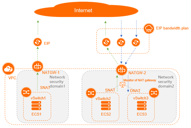
The following scenario is used as an example to show how to deploy multiple Internet NAT gateways in one VPC.

The following content describes the vSwitches used in this example:
Create a VPC, and then create three vSwitches in the VPC. Deploy an Internet NAT gateway (NATGW-1) in Security Domain 1 and another Internet NAT gateway (NATGW-2) in Security Domain 2. Associate vSwitch1 with NATGW-1. Then, associate vSwitch2 and vSwitch3 with NATGW-2.
vSwitch1 belongs to Security Domain 1 and is associated with the system route table. A dedicated public IP address is used to route network traffic. The maximum bandwidth is 50 Mbit/s. The public IP address is not exposed to the Internet. Elastic Compute Service (ECS) instances that are attached to vSwitch1 can send requests to the Internet, but cannot receive requests from the Internet. The ECS instances require a private network environment.
vSwitch2 and vSwitch3 belong to Security Domain 2 and are associated with a subnet route table of the VPC. The ECS instances that are attached to vSwitch 2 share the same egress to communicate with the Internet. They can both send requests to the Internet and receive requests from the Internet. The maximum bandwidth is 1 Gbit/s.
Create a 50 Mbit/s elastic IP address (EIP) named EIP1 and specify EIP1 in an SNAT entry on NATGW-1.
Purchase an Internet Shared Bandwidth of 1 Gbit/s in size, and associate it with NATGW-2. Create three 5 Mbit/s EIPs (EIP2, EIP3, and EIP4), and associate the EIPs with the Internet Shared Bandwidth. Specify an EIP in a DNAT entry for vSwitch2, specify another EIP in a DNAT entry for vSwitch3, and then specify the last EIP in SNAT entries for the two vSwitches.
Configure monitoring for the vSwitches of NATGW-2.
Flowchart

Step 1: Create cloud resources
Before you deploy Internet NAT gateways for vSwitches, you must first create the following cloud resources: a VPC, vSwitches, ECS instances, EIPs, and an Internet Shared Bandwidth.
Cloud resource | Specification | Quantity | References |
VPC | Region: Select China (Hohhot). | 1 | |
vSwitch | Zone:
| 3 | |
ECS instance |
| 3 | |
EIP |
| 4 | |
Internet Shared Bandwidth |
| 1 |
Step 2: Create two Internet NAT gateways
Create two Internet NAT gateways named NATGW-1 and NATGW-2 that are billed on a pay-as-you-go basis in the VPC. Associate NATGW-1 with vSwitch1, and associate NATGW-2 with vSwitch2 and vSwitch3.
- Log on to the NAT Gateway console.
On the Internet NAT Gateway page, click Create Internet NAT Gateway.
When you create an Internet NAT gateway for the first time, click Create in the Notes on Creating Service-linked Roles section of the buy page to create a service-linked role. After the service-linked role is created, you can create Internet NAT gateways.
 For more information, see Service-linked roles.
 On the buy page, set the following parameters and click Buy Now.
Parameter
Description
Billing Method
By default, Pay-As-You-Go is selected. You can pay for resources after you use them. For more information, see Billing of Internet NAT gateways.
Resource Group
Select the resource group to which the virtual private cloud (VPC) belongs. For more information, see Resource group overview.
Tags
Tag Key: Select or enter a tag key.
You can specify at most 20 tag keys. A tag key can be up to 64 characters in length and cannot start with aliyun or acs:. It cannot contain http:// or https://.
Tag Value: Select or enter a tag value.
You can specify at most 20 tag values. A tag value can be up to 128 characters in length. It cannot start with aliyun or acs:, and cannot contain http:// or https://.
Region
Select the region where you want to create the Internet NAT gateway.
VPC
Select the VPC where you want to create the Internet NAT gateway. After the Internet NAT gateway is created, you cannot change the VPC to which the Internet NAT gateway belongs.
Associate vSwitch
Select the vSwitch to which the Internet NAT gateway belongs.
Metering Method
By default, Pay-By-CU is selected. You are charged based on the resources that you use. For more information, see Billing of Internet NAT gateways.
Billing Cycle
By default, By Hour is selected. Bills are generated on an hourly basis. If you use an Internet NAT gateway for less than 1 hour, the usage duration is rounded up to 1 hour.
Instance Name
Enter a name for the Internet NAT gateway.
The name must be 2 to 128 characters in length and can contain digits, underscores (_), and hyphens (-). The name must start with a letter.
Access Mode
Select the mode in which you want to create the Internet NAT gateway. The following modes are supported:
SNAT for All VPC Resources: If you select this value, the Internet NAT gateway is created in unified access mode. After the Internet NAT gateway is created, all resources in the VPC can access the Internet by using the SNAT feature of the NAT gateway.
If you select SNAT for All VPC Resources, you must also specify an EIP.
Configure Later: If you select this option, you can configure the Internet NAT gateway in the console after you complete the payment.
If you select Configure Later, only the Internet NAT gateway is created. No SNAT entry is created.
In this example, Configure Later is selected.
On the Confirm page, confirm the information, select the Terms of Service check box, and then click Confirm.
When the Purchased message appears, the Internet NAT gateway is created.
Step 3: Create a custom route table for vSwitch2 and vSwitch3
A route table consists of one or more route entries. Each route entry specifies the destination to which network traffic is routed. You can use the default route table or create a custom route table to manage network traffic.
Log on to the VPC console.
In the left-side navigation pane, click Route Tables.
Select the region where you want to create a route table.
In this example, China (Hohhot) is selected.
For more information about the regions that support custom route tables, see Route table overview.
On the Route Tables page, click Create Route Table.
In the Create Route Table dialog box, set the following parameters and click OK.
Parameter
Description
Resource Group
Select the resource group to which the route table belongs.
VPC
Select the VPC to which the route table belongs.
Name
Enter a name for the route table.
The name must be 2 to 128 characters in length and can contain digits, underscores (_), and hyphens (-). The name must start with a letter.
Description
Enter a description for the route table.
The description must be 2 to 256 characters in length. It cannot start with
http://orhttps://.On the Route Tables page, find the route table that you want to manage and click its ID.
In the Route Table Details section, click the Associated vSwitch tab and click Associate vSwitch.
In the Associate vSwitch dialog box, select vSwitch2 and click OK. Repeat this step to associate the route table with vSwitch3.
Click the tab and click Add Route Entry. In the Add Route Entry panel, set the following parameters.
Parameter
Description
Name
Enter a name for the route entry.
The name must be 2 to 128 characters in length, and can contain digits, underscores (_), and hyphens (-). It must start with a letter.
Destination CIDR Block
Enter the destination CIDR block to which you want to route traffic. In this example, the destination CIDR block is set to 0.0.0.0/0.
Next Hop Type
NAT Gateway is selected in this example. Traffic destined for the specified CIDR block is routed to the specified NAT gateway.
NAT Gateway
Select
NATGW-2that is created in Step 2: Create two Internet NAT gateways.After you complete the preceding operations, a custom route entry that points to
NATGW-2is added to the newly created custom route table.
Step 4: Associate the three 5 Mbit/s EIPs with an Internet Shared Bandwidth
Log on to the Internet Shared Bandwidth console.
In the top navigation bar, select the region where the Internet Shared Bandwidth is created.
In this example, China (Hohhot) is selected.
On the Internet Shared Bandwidth page, find the EIP bandwidth plan that you want to manage and click AddIP in the Actions column.
In the Add IP panel, click Select from EIP List.Then, select an EIP and click OK.
After you associate the three 5 Mbit/s EIPs with the 1,000 Mbit/s Internet Shared Bandwidth, the EIPs share the 1,000 Mbit/s bandwidth.
Step 5: Associate the four EIPs with the Internet NAT gateways separately
Associate the EIPs with the Internet gateways created in Step 2: Create two Internet NAT gateways. Associate EIP1 with NATGW-1, and associate EIP2, EIP3, and EIP4 with NATGW-2.
- Log on to the NAT Gateway console.
In the top navigation bar, select the region where the Internet NAT gateway is deployed.
In this example, China (Hohhot) is selected.
On the Internet NAT Gateway page, find the Internet NAT gateway that you want to manage and click Associate Now in the Elastic IP Address column.
In the Associate EIP dialog box, set the following parameters and click OK.
Parameter
Description
Resource Group
Select the resource group of the EIP.
EIPs
Select Select Existing EIPs and select an EIP from the drop-down list.
Associate the 50 Mbit/s EIP with
NATGW-1.Associate the other three EIPs with
NATGW-2.
After you complete the preceding operations, the EIPs are displayed in the Elastic IP Address column.
Step 6: Create SNAT entries
ECS instances in VPCs can access the Internet by using SNAT if the ECS instances are not assigned public IP addresses. Create one SNAT entry on NATGW-1, and create two SNAT entries on NATGW-2.
- Log on to the NAT Gateway console.
In the top navigation bar, select the region where the Internet NAT gateway is deployed.
In this example, China (Hohhot) is selected.
- On the Internet NAT Gateway page, find the NAT gateway that you want to manage and click Configure SNAT in the Actions column.
On the SNAT Management tab, click Create SNAT Entry.
On the Create SNAT Entry page, set the parameters and click Confirm.
Configure an SNAT entry on NATGW-1 for vSwitch1.
When you configure SNAT entries on NATGW-2, specify the same EIP in the SNAT entries for vSwitch2 and vSwitch3.
Parameter
Description
SNAT Entry
Specify whether you want to create an SNAT entry for a VPC, a vSwitch, an ECS instance, or a custom CIDR block. Specify vSwitch is selected in this example. The ECS instances that are attached to the specified vSwitch use the EIP to access the Internet.
Select vSwitch: Select a vSwitch from the drop-down list.
NoteIf you select multiple vSwitches, the system creates multiple SNAT entries that use the same EIP.
vSwitch CIDR block: The CIDR block of the selected vSwitch is displayed.
Select EIP
Select one or more EIPs that are used to access the Internet. In this example, Use Single IP is selected and the EIP that is associated with the Internet NAT gateway in Step 2 is selected from the drop-down list.
Entry Name
Enter a name for the SNAT entry.
Step 7: Create DNAT entries
DNAT allows ECS instances to use EIPs on NAT gateways to provide services over the Internet. Create two DNAT entries on NATGW-2.
- Log on to the NAT Gateway console.
In the top navigation bar, select the region where the Internet NAT gateway is deployed.
In this example, China (Hohhot) is selected.
- On the Internet NAT Gateway page, find the NAT gateway that you want to manage and click Configure DNAT in the Actions column.
On the DNAT Management tab, click Create DNAT Entry.
On the Create DNAT Entry page, set the parameters that are described in the following table and click Confirm.
Set the following parameters to create DNAT entries for vSwitch2 and vSwitch3.
Parameter
Description
Select Public IP Address
Select an EIP from the drop-down list. The EIP is used to communicate with the Internet.
Select Private IP Address
Select the ECS instance that uses the DNAT entry to communicate with the Internet. Select Select by ECS or ENI, and then select the ECS instance or the elastic network interface (ENI) associated with the ECS instance from the drop-down list.
Port Settings
Select a DNAT mapping method. Specific Port is selected in this example.
Use the following settings for vSwitch2 and vSwitch3:
vSwitch2:
Public Port: the external port that is used in port forwarding. Port 22 is specified in this example.
Private Port: the internal port that is used in port forwarding. Port 22 is specified in this example.
Protocol Type: the protocol that is used by the ports. TCP is selected in this example.
vSwitch3:
Public Port: the external port that is used in port forwarding. Port 22 is specified in this example.
Private Port: the internal port that is used in port forwarding. Port 22 is specified in this example.
Protocol Type: the protocol that is used by the ports. TCP is selected in this example.
Make sure that the security group rules of ECS2 and ECS3 allow inbound
TCPrequests from port22.Entry Name
Enter a name for the DNAT entry.
The name must be 2 to 128 characters in length, and can contain digits, periods (.), underscores (_), and hyphens (-). It must start with a letter.
Step 8: Test network connectivity and check monitoring metrics
Check whether the ECS instance can access the Internet
Log on to ECS1 in vSwitch1 and perform the following operations to check whether ECS1 can access the Internet. You can also query the EIP specified in the SNAT entry that is associated with ECS1.
Log on to ECS1 in vSwitch1. For more information, see Connection methods.
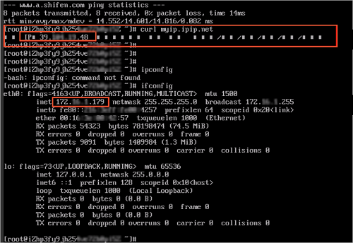
Run the
pingcommand to pingping www.aliyun.com.If you can receive echo reply packets, it indicates that ECS1 can access the Internet.
The result shows that ECS1 can access the Internet.

Run the
curl myip.ipip.netcommand to query the EIP that ECS1 uses to access the Internet. Then, run theifconfigcommand to query the private IP address of ECS1.The result shows that the EIP that the ECS1 uses to access the Internet is the EIP specified in the SNAT entry configured on NATGW-1.

Check whether ECS2 can provide services over the Internet
Log on to an on-premises Linux machine.
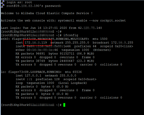
Run the
ssh root@public IP addresscommand. Set the public IP address to the EIP specified in the DNAT entry configured on NATGW-2. Then, enter the password of ECS2 and check if you can access ECS2.If Welcome to Alibaba Cloud Elastic Compute Service! is returned, it indicates that ECS2 can use the DNAT feature of NATGW-2 to provide services over the Internet.

Run the
ifconfigcommand. If the IP address returned is the same as the private IP address of ECS2, it indicates that the ECS2 can provide services over the Internet.
View metrics
- Log on to the NAT Gateway console.
In the top navigation bar, select the region where the Internet NAT gateway is deployed.
On the Internet NAT Gateway page, find the Internet NAT gateway that you want to manage and click
 in the Monitoring column.
 For more information about the monitoring metrics of Internet NAT gateways, see View monitoring data.