This topic describes how to use route maps to stop the communication between a Virtual
Private Cloud (VPC) and other networks that are attached to the same Cloud Enterprise
Network (CEN) instance.
Background information
VPCs can communicate with VPCs, Virtual Border Routers (VBRs), and Cloud Connect Networks
(CCNs) that are attached to the same CEN instance by default. However, you may need
to block the communication between two VPCs, or between a VPC and a VBR or CCN. In
this topic, two VPCs are used as an example to show you how to stop the communication
between two VPCs by using route maps.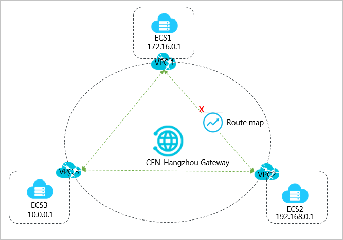
As shown in the preceding figure, VPC1, VPC2, and VPC3 are attached to CEN. By default,
VPC1, VPC2, and VPC3 are all connected and can communicate with each other. By using
route maps, you can block the communication between VPC1 and VPC2 while VPC1 and VPC2
can still communicate with VPC3.
Step 1: Set a route map to deny access from VPC1 to VPC2
To set a route map to deny access from VPC1 to VPC2, follow these steps:
- Log on to the CEN console.
- In the left-side navigation pane, click Instances.
- On the Instances page, find the target CEN instance and click Manage in the Actions column.
- On the CEN page, click the Route Maps tab and then click Add Route Map.
- On the Add Route Map page, configure the route map according to the following information and then click
OK.
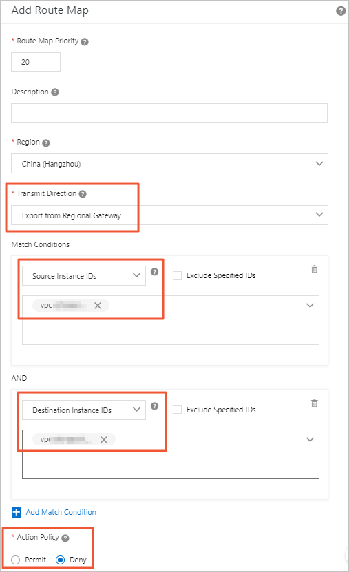
- Route Map Priority: Enter the priority of the route map. A smaller number represents a higher priority.
In this example, enter 20.
- Region: Select the region to which the route map is applied. In this example, select China (Hangzhou).
- Transmit Direction: Select the direction in which the route map is applied. In this example, select
Export from Regional Gateway.
- Match Conditions: Set the match conditions of the route map. In this example, add a match condition
and set the source instance ID to the ID of VPC2 and the destination instance ID to
the ID of VPC1.
- Action Policy: Select the action that is performed to a route if the route meets all the match
conditions. In this example, select Deny.
After you add the route map, you can view the route that denies access from VPC1 to
VPC2 on the
Routes tab.

Step 2: Set a route map to deny access from VPC2 to VPC1
To set a route map to deny access from VPC2 to VPC1, follow these steps:
- In the left-side navigation pane, click Instances.
- On the Instances page, find the target CEN instance and click Manage in the Actions column.
- On the CEN page, click the Route Maps tab and then click Add Route Map.
- On the Add Route Map page, configure the route map according to the following information and then click
OK.
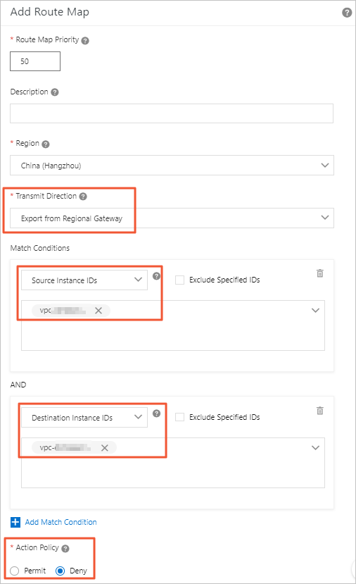
- Route Map Priority: Enter the priority of the route map. A smaller number represents a higher priority.
In this example, enter 50.
- Region: Select the region to which the route map is applied. In this example, select China (Hangzhou).
- Transmit Direction: Select the direction in which the route map is applied. In this example, select
Export from Regional Gateway.
- Match Conditions: Set the match conditions of the route map. In this example, add a match condition
and set the source instance ID to the ID of VPC1 and the destination instance ID to
the ID of VPC2.
- Action Policy: Select the action that is performed to a route if the route meets all the match
conditions. In this example, select Deny.
After you add the route map, you can view the route that denies access from VPC2 to
VPC1 on the
Routes tab.

Step 3: Test the network connectivity
To test the network connectivity between VPC1 and VPC2, follow these steps:
- Log on to the ECS instance ECS1 in VPC1.
- Use the ping command to ping the IP address of the ECS instance ECS2 in VPC2.
The output shows that ECS1 cannot access ECS2, which means VPC1 cannot access VPC2.

- Log on to ECS2 in VPC2.
- Use the ping command to ping the IP address of ECS1 in VPC1.
The output shows that ECS2 cannot access ECS1, which means VPC2 cannot access VPC1.

To test the network connectivity between VPC1 and VPC3, follow these steps:
- Log on to ECS1 in VPC1.
- Use the ping command to ping the IP address of ECS3 in VPC3.
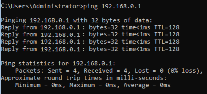
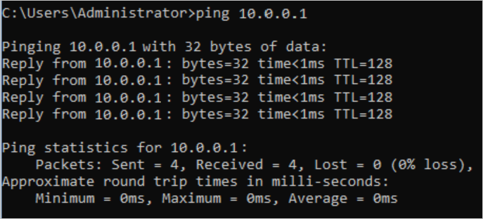
The output shows that ECS1 can access ECS3, which means VPC1 can access VPC3.
- Log on to ECS3 in VPC3.
- Use the ping command to ping the IP address of ECS1 in VPC1.
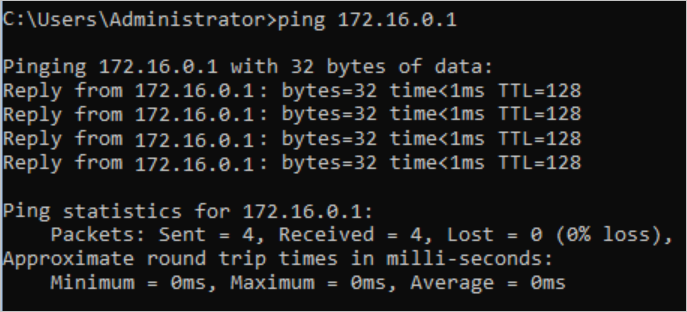
The output shows that ECS3 can access ECS1, which means VPC3 can access VPC1.
To test the network connectivity between VPC2 and VPC3, follow these steps:
- Log on to ECS2 in VPC2.
- Use the ping command to ping the IP address of ECS3 in VPC3.
The output shows that ECS2 can access ECS3, which means VPC2 can access VPC3.

- Log on to ECS3 in VPC3.
- Use the ping command to ping the IP address of ECS2 in VPC2.
The output shows that ECS3 can access ECS2, which means VPC3 can access VPC2.
