This topic describes how to use routing policies of Cloud Enterprise Network (CEN) to connect the branches of an enterprise to the data center of the enterprise.
Prerequisites
This feature is supported only by Basic Edition transit routers.
A Cloud Connect Network (CCN) instance is created. Smart Access Gateway (SAG) instances that are used by the branches are attached to the CCN instance. For more information, see Get started with the SAG app and Deploy an SAG device in inline mode.
A CEN instance is created. The network instances that you want to connect to each other are attached to the CEN instance. For more information, see CEN instances, Create a CCN connection and Connect a VBR to a Basic Edition transit router.
A bandwidth plan is purchased and bandwidth for inter-region communication is allocated. For more information, see Work with a bandwidth plan and Manage inter-region connections.
Background information
The system automatically adds a default routing policy to the transit router of a CEN instance. The priority value of the default routing policy is 5000 and the action policy is Reject. This routing policy forbids the virtual border routers (VBRs) and the CCN instances that are attached to the CEN instance to communicate with each other. However, in some scenarios, you may need to allow the VBRs and CCN instances to communicate with those that are also attached to the CEN instance.

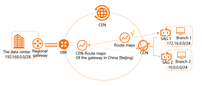
The proceeding figure shows that the data center of an enterprise is deployed in the China (Beijing) region. The data center is connected to Alibaba Cloud by using a VBR. A branch of the enterprise (Branch 1) is located in the China (Shanghai) region. Another branch of the enterprise (Branch 2) is located in the China (Hangzhou) region. Branch 1 is connected to a CCN instance by using an SAG instance (SAG 1). Branch 2 is connected to the same CCN instance by using another SAG instance (SAG 2). By default, the data center cannot communicate with Branch 1 or Branch 2. You can add a routing policy to allow the data center and Branch 1 to communicate with each other.
Step 1: Add a routing policy to allow the data center to access Branch 1
Perform the following steps to add a routing policy to allow the data center to access Branch 1:
Log on to the CEN console.
On the Instances page, click the CEN instance that you want to manage.
On the instance details page, find the region where you want to add a routing policy and click the transit router in the region.
On the details page of the transit router, click the Route Table tab and click Routing Policies.
On the Routing Policies tab, click Add Routing Policy. Set the following parameters and click OK:
Routing Policy Priority: Enter a priority value for the routing policy. A smaller value indicates a higher priority. In this example, 20 is entered.
Region: Select the region to which you want to apply the routing policy. In this example, China (Beijing) is selected.
Policy Direction: Select the direction in which you want to apply the routing policy. In this example, Egress Regional Gateway is selected.
Match Conditions: Configure match conditions for the routing policy. In this example, the following match conditions are specified:
Source Instance ID List: The ID of SAG 1 is selected.
Destination Instance ID List: The ID of the VBR is selected.
Route Prefix: Select Exact Match. 172.16.0.0/24 is used.
Action Policy: Select the action that you want to perform on routes that meet the match conditions. In this example, Allow is selected.
After you add the routing policy, you can go to the Network Routes tab to view the routes that allow the data center to access Branch 1.

Step 2: Add a routing policy to allow the CCN instance to access the data center
Perform the following steps to add a routing policy to allow the CCN instance to access the data center:
Log on to the CEN console.
On the Instances page, click the CEN instance that you want to manage.
On the instance details page, find the region where you want to add a routing policy and click the transit router in the region.
On the details page of the transit router, click the Route Table tab and click Routing Policies.
On the Routing Policies tab, click Add Routing Policy. Set the following parameters and click OK:
Routing Policy Priority: Enter a priority value for the routing policy. A smaller value indicates a higher priority. In this example, 20 is entered.
Region: Select the region to which you want to apply the routing policy. In this example, Chinese Mainland CCN is selected.
Policy Direction: Select the direction in which you want to apply the routing policy. In this example, Egress Regional Gateway is selected.
Match Conditions: Configure match conditions for the routing policy. In this example, the following match conditions are specified:
Source Instance ID List: The ID of the VBR is selected.
Target Instance ID List: the ID of the CCN instance is selected.
Route Prefix: Select Exact Match. 192.168.0.0/24 is used.
Action Policy: Select the action that you want to perform on routes that meet the match conditions. In this example, Allow is selected.
After you add the routing policy, you can go to the Network Routes tab to view the routes that allow the CCN instance to access the data center.

Step 3: Test network connectivity
Perform the following steps to test the network connectivity between the data center and Branch 1:
Open the command-line window in the client of the data center.
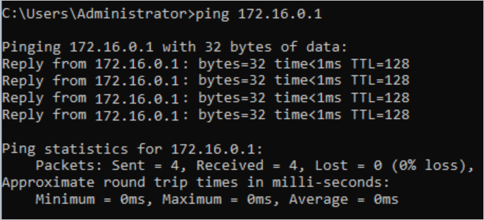
Run the ping command to access the IP address of the client in Branch 1.
The result shows that the data center can access Branch 1.

Open the command-line window in the client in Branch 1.
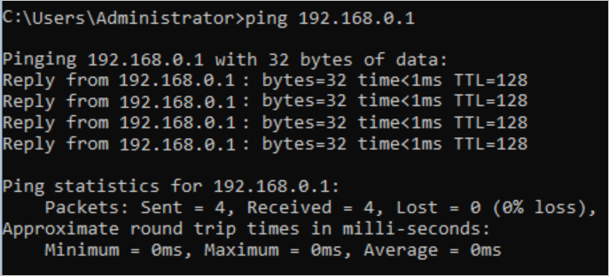
Run the ping command to access the IP address of the client in the data center.
The result shows that Branch 1 can access the data center.

Perform the following steps to test the network connectivity between the data center and Branch 2:
Open the command-line window in the client of the data center.
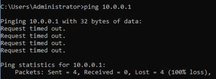
Run the ping command to access the IP address of the client in Branch 2.
The result shows that the data center cannot access Branch 2.
