This topic describes how to connect a third-party SD-WAN appliance to a transit router to enable network communication between data centers (IDCs) and virtual private clouds (VPCs) on Alibaba Cloud.
Example scenario
This topic contains information about third-party products. This information is for reference only. Alibaba Cloud makes no representations or warranties, express or implied, with respect to the performance and reliability of third-party products, or potential impacts of using these products.
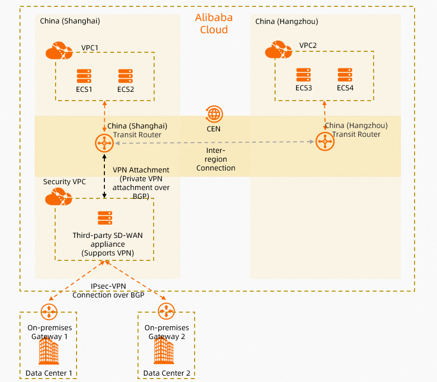
This topic uses the scenario shown in the following figure. A company has two data centers, IDC1 and IDC2, in the China (Shanghai) region. The company also has a service VPC, VPC1, in the China (Shanghai) region and another service VPC, VPC2, in the China (Hangzhou) region. The company needs to enable communication among IDC1, IDC2, VPC1, and VPC2. The company wants to connect IDC1 and IDC2 to Alibaba Cloud through a third-party SD-WAN appliance. This allows the company to configure access control policies on the appliance for secure access. The company also wants to enable automatic route advertisement and learning between Alibaba Cloud and the data centers to reduce routing maintenance.
The company can connect the third-party SD-WAN appliance directly to a transit router using a VPN connection. The data centers then communicate with the VPCs through the SD-WAN appliance and the transit router. Border Gateway Protocol (BGP) is used on the transit routers, the SD-WAN appliance, IDC1, and IDC2 to enable automatic route advertisement and learning.
Network planning
Network features
Create an Elastic Compute Service (ECS) instance in a separate VPC, referred to as the security VPC in this topic. Then, deploy a third-party SD-WAN appliance on the ECS instance by installing a third-party image.
In this topic, the FortiGate V6.2.4 image is installed on the ECS instance in the security VPC to deploy a third-party SD-WAN appliance.
The third-party SD-WAN appliance and the transit router can be directly connected using a VPN connection. The VPN connection uses the Private gateway type.
Use BGP dynamic routing between the third-party SD-WAN appliance and the transit router to propagate routes. This enables automatic route advertisement and learning.
Establish an IPsec-VPN connection between the third-party SD-WAN appliance and IDC1, and another between the appliance and IDC2. This connects IDC1 and IDC2 to Alibaba Cloud.
Use Auto Discovery VPN (ADVPN) to establish a full-mesh IPsec-VPN connection between the third-party SD-WAN appliance, IDC1, and IDC2. For more information about ADVPN, see the Fortinet documentation.
The third-party SD-WAN appliance, on-premises gateway device 1, and on-premises gateway device 2 all use BGP dynamic routing. An iBGP peer relationship is established to enable automatic route advertisement and learning.
In this topic, both on-premises gateway device 1 and on-premises gateway device 2 are Fortinet devices with the FortiGate V6.2.4 image installed.
CIDR block planning
When you plan CIDR blocks, make sure that the CIDR blocks of the networks that you want to connect do not overlap.
Table 1. Basic CIDR block planning
Resource | CIDR block and IP address |
Service VPC1 |
|
Service VPC2 |
|
Security VPC |
|
IDC1 |
|
IDC2 |
|
Table 2. BGP address planning
Resource | BGP AS number | Local BGP IP address | Peer BGP IP address |
BGP configuration between the third-party SD-WAN appliance and the transit router | |||
IPsec-VPN connection | 65531 | 169.254.20.1 | 169.254.20.2 |
Third-party SD-WAN appliance | 65534 | 169.254.20.2 | 169.254.20.1 |
BGP configuration between the third-party SD-WAN appliance and IDC1 | |||
IDC1 | 65534 | 169.254.10.10 | 169.254.10.1 |
Third-party SD-WAN appliance | 65534 | 169.254.10.1 | 169.254.10.10 |
BGP configuration between the third-party SD-WAN appliance and IDC2 | |||
IDC2 | 65534 | 169.254.10.11 | 169.254.10.1 |
Third-party SD-WAN appliance | 65534 | 169.254.10.1 | 169.254.10.11 |
Preparations
Before you begin, complete the following operations:
Create service VPC1 and a security VPC in the China (Shanghai) region, and service VPC2 in the China (Hangzhou) region. Then, use ECS instances to deploy related services. For more information, see Create a VPC with an IPv4 CIDR block.
Deploy applications on the ECS instances in service VPC1 and service VPC2 as needed.
On the ECS instance in the security VPC, install a third-party image to deploy a third-party SD-WAN appliance. In this topic, the FortiGate V6.2.4 image is installed. Make sure that the third-party SD-WAN appliance has a public IP address. You can install a third-party image on an ECS instance from the Alibaba Cloud Marketplace. For more information, see Alibaba Cloud Marketplace images.
Create a CEN instance. For more information, see Create a CEN instance.
Configuration flow
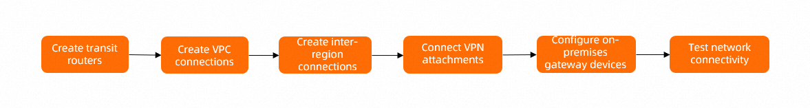
Step 1: Create transit router instances
To use CEN to enable communication between your data centers and VPCs, you must create a transit router in the China (Shanghai) region and another in the China (Hangzhou) region. You must also assign a CIDR block to the transit router in the China (Shanghai) region. This CIDR block is used for the VPC and VPN connections.
Log on to the CEN console.
On the Instances page, find the CEN instance that you created in the Preparations section and click the instance ID.
On the tab, click Create Transit Router.
In the Create Transit Router dialog box, configure the transit router and click OK.
The following table describes only the parameters that are relevant to this topic. Keep the default values for other parameters. For more information, see Transit router CIDR blocks.
Configuration
Description
China (Shanghai) region
China (Hangzhou) region
Region
Select the region where you want to create the transit router.
In this topic, select China (Shanghai).
In this topic, select China (Hangzhou).
Edition
The edition of the transit router.
The system automatically determines and displays the edition of the transit router in the current region.
Enable Multicast
Specify whether to enable the multicast feature for the transit router.
In this topic, keep the default value. The multicast feature is not enabled.
Name
Enter a name for the transit router.
In this topic, enter TR-shanghai.
In this topic, enter TR-hangzhou.
TR CIDR Block
Enter a CIDR block for the transit router.
A transit router CIDR block is a custom CIDR block that you specify for a transit router. It is similar to a loopback interface CIDR block. IP addresses from the transit router CIDR block are assigned to IPsec-VPN connections. For more information, see Transit router CIDR blocks.
In this topic, enter 10.10.10.0/24.
In this topic, do not enter a transit router CIDR block.
Step 2: Create VPC connections
You must connect service VPC1, the security VPC, and service VPC2 to the transit routers in their respective regions. This allows the data centers and VPCs to communicate with each other through the transit routers.
On the Instances page, find the CEN instance that you created in the Preparations section and click the instance ID.
On the tab, find the transit router that you created in Step 1. In the Actions column, click Create Connection.
On the Connection with Peer Network Instance page, configure the parameters and click OK.
The following table describes only the parameters that are relevant to this topic. Keep the default values for other parameters. For more information, see Create a VPC connection.
Configuration
Description
Service VPC1
Security VPC
Service VPC2
Instance Type
Select the type of network instance.
In this topic, select Virtual Private Cloud (VPC).
In this topic, select Virtual Private Cloud (VPC).
In this topic, select Virtual Private Cloud (VPC).
Region
Select the region of the network instance.
In this topic, select China (Shanghai).
In this topic, select China (Shanghai).
In this topic, select China (Hangzhou).
Transit Router
The system automatically displays the ID of the transit router that is created in the current region.
Resource Owner UID
Select whether the network instance belongs to the current Alibaba Cloud account.
In this topic, select Current Account.
In this topic, select Current Account.
In this topic, select Current Account.
Billing Method
The billing method of the VPC connection. The default value is Pay-as-you-go. For more information about the billing of transit routers, see Billing.
Connection Name
Enter a name for the VPC connection.
In this topic, enter Service VPC1 connection.
In this topic, enter Security VPC connection.
In this topic, enter Service VPC2 connection.
Network Instance
Select a network instance.
In this topic, select service VPC1.
In this topic, select the security VPC.
In this topic, select service VPC2.
VSwitch
Select the vSwitches in the zones that the transit router supports.
If the Enterprise Edition transit router is deployed in a region that supports only one zone, select a vSwitch in the zone.
If it is deployed in a region that supports multiple zones, select at least two vSwitches that are in different zones for zone-disaster recovery. This ensures uninterrupted data transmission between the VPC and the transit router.
We recommend that you select a vSwitch in each zone to reduce latency and improve network performance because data can be transmitted over a shorter distance.
Make sure that each selected vSwitch has an idle IP address.If the VPC does not have a vSwitch in the zones supported by the transit router, or if the vSwitch does not have an idle IP address, you need to create a new vSwitch. For more information, see Create and manage vSwitches.
In this topic, select vSwitch 1 in Shanghai Zone F and vSwitch 2 in Shanghai Zone G.
In this topic, select vSwitch 1 in Shanghai Zone F and vSwitch 2 in Shanghai Zone G.
In this topic, select vSwitch 1 in Hangzhou Zone I and vSwitch 2 in Hangzhou Zone H.
Advanced Configuration
Select the advanced features that you want to enable.
In this topic, keep the default configuration. All advanced features are enabled.
In this topic, keep the default configuration. All advanced features are enabled.
In this topic, keep the default configuration. All advanced features are enabled.
Step 3: Create an inter-region connection
Service VPC1 and the security VPC can communicate with each other because they are connected to the same transit router. However, they cannot communicate with service VPC2 because service VPC2 is connected to a transit router in a different region. To enable inter-region communication, you must create an inter-region connection between the transit routers in the China (Shanghai) and China (Hangzhou) regions. This enables communication between service VPC1 and service VPC2, and between the security VPC and service VPC2.
On the CEN Instances page, find the destination CEN instance and click the instance ID.
On the tab, click Allocate Bandwidth for Inter-region Communication.
On the Connect with Peer Network Instance page, configure the inter-region connection and click OK.
Create an inter-region connection with the following information. Keep the default values for other parameters. For more information, see Create an inter-region connection.
Configuration
Description
Instance Type
Select Inter-region Connection.
Region
Select the region that you want to connect.
In this topic, select China (Hangzhou).
Transit Router
The system automatically displays the ID of the transit router instance in the current region.
Connection Name
Enter a name for the inter-region connection.
In this topic, enter Inter-region connection.
Peer Region
Select the peer region that you want to connect.
In this topic, select China (Shanghai).
Transit Router
The system automatically displays the ID of the transit router instance in the current region.
Bandwidth Allocation Method
Inter-region connections support the following bandwidth allocation methods:
Allocate From Bandwidth Plan: allocates bandwidth from a purchased bandwidth plan.
Pay-by-data Transfer: charges you for the actual traffic of the inter-region connection.
In this topic, select Pay-by-data Transfer.
Bandwidth
Enter a bandwidth value for the inter-region connection. Unit: Mbit/s.
Default Link Type
Use the default link type.
Advanced Configuration
Keep the default configuration. All advanced configuration options are selected.
Step 4: Create a VPN connection
After you complete the preceding steps, service VPC1, service VPC2, and the security VPC can communicate with each other. However, the transit router and the security VPC cannot learn the routes of the data centers. You must create a VPN connection between the third-party SD-WAN appliance and the transit router, and between the third-party SD-WAN appliance and the data centers. This allows the third-party SD-WAN appliance to learn the routes of the data centers and advertise them to the transit router through the VPN connection.
Log on to the VPN Gateway console.
Create a customer gateway.
Before you create a VPN connection between the third-party SD-WAN appliance and the transit router, you must create a customer gateway to register the information about the third-party SD-WAN appliance with Alibaba Cloud.
In the left-side navigation pane, choose .
In the top navigation bar, select the region where you want to create the customer gateway.
Select the region where the VPC that contains the third-party SD-WAN appliance is deployed. In this topic, select China (Shanghai).
On the Customer Gateway page, click Create Customer Gateway.
In the Create Customer Gateway panel, configure the parameters and click OK.
The following table describes only the parameters that are relevant to this topic. Keep the default values for other parameters. For more information, see Create and manage a customer gateway.
Configuration
Description
Customer gateway
Name
Enter a name for the customer gateway.
In this topic, enter Customer-Gateway.
IP Address
Enter the IP address of the third-party SD-WAN appliance that is used to create the VPN connection.
In this topic, enter the private IP address of the third-party SD-WAN appliance, 172.16.0.15.
ASN
Enter the BGP AS number (ASN) of the third-party SD-WAN appliance.
In this topic, enter 65534.
Create an IPsec-VPN connection.
After you create the customer gateway, you must create an IPsec-VPN connection on Alibaba Cloud. The transit router uses the IPsec-VPN connection to establish a VPN connection with the third-party SD-WAN appliance.
In the left-side navigation pane, choose .
In the top navigation bar, select the region where you want to create the IPsec-VPN connection.
The IPsec-VPN connection and the customer gateway must be in the same region. In this topic, select China (Shanghai).
On the IPsec Connections page, click Bind CEN.
On the Create IPsec-VPN Connection page, configure the IPsec-VPN connection and click OK.
You are charged for creating an IPsec-VPN connection. For more information about the billing of IPsec-VPN connections, see Billing.
Configuration
Description
IPsec-VPN connection
Name
Enter a name for the IPsec-VPN connection.
In this topic, enter IPsec-VPN connection.
Region
Select the region of the transit router to which you want to attach the connection.
After the IPsec-VPN connection is created, it is in the same region as the transit router.
Select China (Shanghai).
Gateway Type
Select the network type of the IPsec-VPN connection.
In this topic, select Private.
The security VPC is already connected to the transit router. The third-party SD-WAN appliance can establish a VPN connection with the transit router over a private network.
Bind CEN
Select the account to which the transit router belongs.
Select Same Account.
CEN Instance ID
Select a CEN instance.
In this topic, select the CEN instance that you created in the Preparations section.
Routing Mode
Select a routing mode.
In this topic, select Destination Routing Mode.
Effective Immediately
Specify whether the configuration of the IPsec-VPN connection takes effect immediately. Valid values:
Yes: Negotiations start immediately after the configuration is complete.
No: Negotiations start when traffic is detected.
In this topic, select Yes.
Customer Gateway
Select the customer gateway to associate with the IPsec-VPN connection.
In this topic, select Customer-Gateway.
Pre-shared Key
Enter the authentication key for the IPsec-VPN connection. This key is used for identity authentication between the on-premises gateway device and the IPsec-VPN connection.
The key must be 1 to 100 characters in length and can contain digits, uppercase letters, lowercase letters, and the following special characters:
~`!@#$%^&*()_-+={}[]\|;:',.<>/?. The key cannot contain space characters.If you do not specify a pre-shared key, the system generates a random 16-character string as the pre-shared key. After you create the IPsec-VPN connection, you can view the pre-shared key generated by the system by clicking the Edit button of the tunnel. For more information, see Modify tunnel configurations.
ImportantThe IPsec-VPN connection and the peer gateway device must use the same pre-shared key. Otherwise, the system cannot establish an IPsec-VPN connection.
In this topic, enter fddsFF123****.
Enable BGP
Specify whether to enable BGP. BGP is disabled by default.
In this topic, enable BGP.
Local ASN
Enter the ASN for the IPsec-VPN connection. The default value is 45104. The value can be an integer from 1 to 4294967295.
In this topic, enter 65531.
Encryption Configuration
Add encryption configurations, such as IKE and IPsec configurations.
Except for the following parameters, keep the default values.
For IKE Configurations, set Encryption Algorithm to des.
For IPsec Configurations, set Encryption Algorithm to des.
NoteYou need to select encryption parameters based on the on-premises gateway device to ensure that the encryption configurations for the IPsec connection are the same as those for the on-premises gateway device.
BGP Configuration
Tunnel CIDR Block
Enter the CIDR block to establish the encrypted tunnel.
This CIDR block must be within the 169.254.0.0/16 range and have a 30-bit subnet mask.
The CIDR block must fall into 169.254.0.0/16. The mask of the CIDR block must be 30 bits in length. The CIDR block cannot be 169.254.0.0/30, 169.254.1.0/30, 169.254.2.0/30, 169.254.3.0/30, 169.254.4.0/30, 169.254.5.0/30, 169.254.6.0/30, or 169.254.169.252/30.
In this topic, enter 169.254.20.0/30.
Local BGP IP address
Enter the BGP IP address for the IPsec-VPN connection.
This address must be an IP address within the tunnel CIDR block.
In this topic, enter 169.254.20.1.
Advanced Configuration
Specify whether to enable advanced configurations for the IPsec-VPN connection.
In this topic, keep the default value. All advanced configurations are enabled.
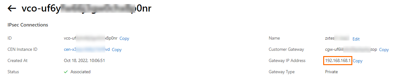
After the IPsec-VPN connection is created, the system automatically assigns a gateway IP address to it. This address is used to establish the VPN connection between the IPsec-VPN connection and the third-party SD-WAN appliance. You can view the gateway IP address on the details page of the IPsec-VPN connection, as shown in the following figure.
 Note
NoteThe system assigns a gateway IP address to an IPsec-VPN connection only after the connection is attached to a transit router. If you set Associated Resource to Not Associated or VPN Gateway when you create the IPsec-VPN connection, the system does not assign a gateway IP address.
After a private IPsec-VPN connection is attached to a transit router, the system automatically advertises the gateway IP address of the IPsec-VPN connection to the route table of the transit router.
Download the peer configuration of the IPsec-VPN connection.
Return to the IPsec Connections page. Find the IPsec-VPN connection that you just created and click Generate Peer Configuration in the Actions column.
Add VPN and BGP configurations to the third-party SD-WAN appliance.
After you create the IPsec-VPN connection, add VPN and BGP configurations to the third-party SD-WAN appliance based on the downloaded peer configuration and the following steps. This establishes a VPN connection between the third-party SD-WAN appliance and the transit router.
NoteThis topic uses a FortiGate firewall (software version V6.2.4) as an example. Configuration commands may vary depending on the software version. When performing the operations, refer to the relevant documentation or consult the vendor based on your environment. For more examples of on-premises gateway device configurations, see On-premises gateway device configuration examples.
The following content contains information about third-party products. This information is for reference only. Alibaba Cloud makes no representations or warranties, express or implied, with respect to the performance and reliability of these products, or potential impacts of operations performed using these products.
Log on to the command-line interface (CLI) of the third-party SD-WAN appliance.
Add the phase 1 configuration (IKE configuration) for the IPsec-VPN connection to the third-party SD-WAN appliance.
# Add the phase 1 configuration for the IPsec-VPN connection for Tunnel 1.
config vpn ipsec phase1-interface
 edit "to_aliyun_test1"
 set interface "port1"             # Use port1 to establish a VPN connection with the transit router.
 set ike-version 2
 set peertype any
 set net-device disable
 set proposal des-sha1             # Configure the phase 1 encryption and authentication algorithms. The settings must be the same as the phase 1 (IKE) configuration of the IPsec-VPN connection.
 set localid-type address          # Set the local ID format to IP address. This must be the same as the RemoteId format of the Alibaba Cloud IPsec-VPN connection.
 set dhgrp 2                       # Configure the phase 1 DH group. The setting must be the same as the phase 1 (IKE) configuration of the IPsec-VPN connection.
 set remote-gw 192.168.168.1       # Specify the IP address of the peer of the third-party SD-WAN appliance. This is the gateway IP address of the IPsec-VPN connection.
 set psksecret fddsFF123****       # Specify the pre-shared key for the tunnel. The pre-shared keys on the Alibaba Cloud IPsec-VPN connection and the third-party SD-WAN appliance must be the same.
 next
end
Add the phase 2 configuration (IPsec configuration) for the IPsec-VPN connection to the third-party SD-WAN appliance.
# Add the phase 2 configuration for the IPsec-VPN connection for the tunnel.
config vpn ipsec phase2-interface
    edit "to_aliyun_test1"
        set phase1name "to_aliyun_test1"    # Associate the tunnel with the phase1-interface.
        set proposal des-sha1               # Configure the phase 2 encryption and authentication algorithms. The settings must be the same as the phase 2 (IPsec) configuration of the IPsec-VPN connection.
        set dhgrp 2                         # Configure the phase 2 DH group. The setting must be the same as the phase 2 (IPsec) configuration of the IPsec-VPN connection.
        set auto-negotiate enable
        set keylifeseconds 86400            # Configure the SA lifetime.
    next
end
Configure the BGP IP address for the tunnel interface.
config system interface
    edit "to_aliyun_test1"
        set ip 169.254.20.2 255.255.255.255          # Configure the BGP IP address of the tunnel interface.
        set type tunnel                              # Specify the tunnel interface type.
        set remote-ip 169.254.20.1 255.255.255.255   # Specify the BGP IP address of the tunnel peer.
        set interface "port1"                        # Associate the tunnel with the physical interface "port1".
    next
end
Configure a firewall policy.
config firewall policy
    edit 1
        set name "forti_to_aliyun1"       # Configure a security policy for traffic from the third-party SD-WAN appliance to Alibaba Cloud.
        set srcintf "port1"               # The source interface is "port1".
        set dstintf "to_aliyun_test1"     # The destination interface is the VPN connection tunnel interface.
        set srcaddr "all"                 # Match traffic from all source CIDR blocks.
        set dstaddr "all"                 # Match traffic to all destination CIDR blocks.
        set action accept                 # Allow traffic.
        set schedule "always"
        set service "ALL"
    next
    edit 2
        set name "aliyun_to_forti1"       # Configure a security policy for traffic from Alibaba Cloud to the third-party SD-WAN appliance.
        set srcintf "to_aliyun_test1"     # The source interface is the VPN connection tunnel interface.
        set dstintf "port1"               # The destination interface is "port1".
        set srcaddr "all"                 # Match traffic from all source CIDR blocks.
        set dstaddr "all"                 # Match traffic to all destination CIDR blocks.
        set action accept                 # Allow traffic.
        set schedule "always"
        set service "ALL"
    next
end
Configure BGP dynamic routing.
config router bgp
    set as 65534
    set router-id 172.16.0.15
    config neighbor
        edit "169.254.20.1"                       # Specify the BGP peer of the tunnel.
            set remote-as 65531
        next
    end
    config network
        edit 1
            set prefix 172.16.0.0 255.255.0.0    # Advertise the CIDR block of the security VPC that needs to communicate with other networks.
        next
    end
end
Step 5: Configure the on-premises gateway devices
You need to add VPN and BGP configurations on on-premises gateway device 1, on-premises gateway device 2, and the third-party SD-WAN appliance. This establishes IPsec-VPN connections among them and enables communication between IDC1 and IDC2, and between the data centers and the VPCs on Alibaba Cloud.
Use Auto Discovery VPN (ADVPN) to establish a full-mesh IPsec-VPN connection between the third-party SD-WAN appliance, IDC1, and IDC2. For more information about ADVPN, see the Fortinet documentation.
This topic uses a FortiGate firewall (software version V6.2.4) as an example. Configuration commands may vary depending on the software version. When performing the operations, refer to the relevant documentation or consult the vendor based on your environment. For more examples of on-premises gateway device configurations, see On-premises gateway device configuration examples.
Third-party SD-WAN appliance configuration example
Make sure that UDP ports 500 and 5000 on the third-party SD-WAN appliance allow access from the public IP addresses of on-premises gateway device 1 and on-premises gateway device 2. For more information, see Add a security group rule.
Log on to the CLI of the third-party SD-WAN appliance.
Run the following command to add the phase 1 configuration for the IPsec-VPN connection.
config vpn ipsec phase1-interface
    edit "HUB"                                              # Set the third-party SD-WAN appliance as the hub node.
        set type dynamic
        set interface "port1"                               # Use port1 to establish an IPsec-VPN connection to the data center.
        set ike-version 2                                   # Use IKEv2.
        set peertype any
        set net-device disable                              # Disable this feature.
        set proposal des-sha1                               # Configure the phase 1 encryption and authentication algorithms.
        set add-route disable                               # Disable automatic route advertisement.
        set dpd on-idle
        set wizard-type hub-fortigate-auto-discovery
        set auto-discovery-sender enable                    # Enable this feature on the hub node to receive and send information about direct tunnels between spokes.
        set network-overlay enable
        set network-id 1
        set psksecret fddsFF456****                         # Configure the pre-shared key.
        set dpd-retryinterval 60
    next
end
Run the following command to add the phase 2 configuration for the IPsec-VPN connection.
config vpn ipsec phase2-interface
    edit "HUB"
        set phase1name "HUB"
        set proposal des-sha1                          # Configure the phase 2 encryption and authentication algorithms.
    next
end
Run the following command to configure the IP address of the IPsec-VPN tunnel.
config system interface edit "HUB" set vdom "root" set ip 169.254.10.1 255.255.255.255 # Configure the tunnel IP address. set allowaccess ping set type tunnel # Specify the tunnel interface type. set remote-ip 169.254.10.254 255.255.255.0 # Configure the IP address of the tunnel peer. set interface "port1" # Associate the tunnel with the physical interface "port1". next endImportant169.254.10.254 is a reserved IP address that is not used by spoke nodes. An IPsec-VPN tunnel is a point-to-point tunnel. However, in ADVPN, this tunnel needs to connect to multiple spoke nodes simultaneously. Therefore, you cannot set remote-ip to the IP address of an existing spoke node.
Run the following command to configure a security policy on the third-party SD-WAN appliance to allow communication between the data centers, and between the data centers and Alibaba Cloud.
config firewall policy
    edit 7
        set name "HUB_to_SPOKE"
        set srcintf "port1" "HUB" "to_aliyun_test1"     # The source interfaces are "port1", "HUB", and "to_aliyun_test1".
        set dstintf "HUB" "port1" "to_aliyun_test1"     # The destination interfaces are "port1", "HUB", and "to_aliyun_test1".
        set action accept                               # Allow traffic.
        set srcaddr "all"                               # Match traffic from all source CIDR blocks.
        set dstaddr "all"                               # Match traffic to all destination CIDR blocks.
        set schedule "always"
        set service "ALL"
    next
end
Run the following command to add a BGP configuration.
config router bgp
    set as 65534                                           # Specify the BGP ASN of the third-party SD-WAN appliance as 65534.
    config neighbor-group                                  # Enable the neighbor-group property.
        edit "HUB_group"
            set next-hop-self enable
            set remote-as 65534                            # Specify the BGP ASN of the peer.
            set additional-path send
            set route-reflector-client enable              # Enable the route reflection feature and specify the third-party SD-WAN appliance as the route reflector.
        next
    end
    config neighbor-range
        edit 1
            set prefix 169.254.10.0 255.255.255.0          # BGP peers that match the prefix list 169.254.10.0/24 can establish an iBGP peer relationship with the hub node.
            set neighbor-group "HUB_group"
        next
    end
end
On-premises gateway device 1 configuration example
Log on to the CLI of on-premises gateway device 1.
Add a default route to ensure that on-premises gateway device 1 can access the public IP address of the third-party SD-WAN appliance.
# In this scenario, the port1 interface is mapped to the public IP address 121.XX.XX.211. Therefore, configure the default route to point to the port1 gateway.
config router static
    edit 1
        set device "port1"
        set distance 5
        set gateway 192.168.100.253
    next
end

# You can run the following command to view routing information.
FortiGate-VM64-KVM # get router info routing-table all
S*      0.0.0.0/0 [5/0] via 192.168.100.253, port1
Run the following command to add the phase 1 configuration for the IPsec-VPN connection.
config vpn ipsec phase1-interface
    edit "hz_sp"
        set interface "port1"                           # Use the "port1" interface to establish an IPsec-VPN connection with the third-party SD-WAN appliance.
        set ike-version 2                               # Use IKEv2.
        set peertype any
        set net-device disable                          # Disable this feature.
        set proposal des-sha1                           # Configure the phase 1 encryption and authentication algorithms.
        set localid "hzoffice1"
        set dpd on-idle
        set wizard-type spoke-fortigate-auto-discovery
        set auto-discovery-receiver enable               # Enable this feature on the spoke node to receive information about direct tunnels from the hub node.
        set network-overlay enable
        set network-id 1
        set remote-gw 42.XX.XX.129                       # Specify the public IP address of the hub node.
        set psksecret fddsFF456****                      # Configure the pre-shared key. It must be the same as the key on the hub node.
        set add-route disable                            # Disable automatic route advertisement.
    next
end
Run the following command to add the phase 2 configuration for the IPsec-VPN connection.
config vpn ipsec phase2-interface
    edit "hz_sp"
        set phase1name "hz_sp"
        set proposal des-sha1                         # Configure the phase 2 encryption and authentication algorithms.
        set auto-negotiate enable                     # Enable autonegotiation.
    next
end
Run the following command to configure the IP address of the IPsec-VPN tunnel.
config system interface
    edit "hz_sp"
        set vdom "root"
        set ip 169.254.10.10 255.255.255.255           # Configure the tunnel IP address.
        set allowaccess ping
        set type tunnel                                # Specify the tunnel interface type.
        set remote-ip 169.254.10.254 255.255.255.0     # Configure the IP address of the tunnel peer.
        set interface "port1"                          # Associate the tunnel with the physical interface "port1".
    next
end

config system interface                                # Create a loopback interface to simulate a client in IDC1.
    edit "loopback"
       set vdom "root"
       set ip 192.168.254.100 255.255.255.0
       set allowaccess ping
       set type loopback
  next
end
Run the following command to configure a security policy on on-premises gateway device 1 to allow communication between the data centers, and between the data centers and Alibaba Cloud.
config firewall policy
    edit 3
        set name "hz_sp_remote"                    # Configure a security policy for traffic destined for IDC1.
        set srcintf "hz_sp"  "loopback" "port1"    # The source interfaces are "port1", "hz_sp", and "loopback".
        set dstintf "loopback" "hz_sp" "port1"     # The destination interfaces are "port1", "hz_sp", and "loopback".
        set action accept                # Allow traffic.
        set srcaddr "all"                # Match traffic from all source CIDR blocks.
        set dstaddr "all"                # Match traffic to all destination CIDR blocks.
        set schedule "always"
        set service "ALL"
    next
end
Run the following command to add a BGP configuration.
config router bgp
    set as 65534                                         # Specify the BGP ASN of on-premises gateway device 1.
    set network-import-check disable                     # Disable the check for advertised routes.
    config neighbor
        edit "169.254.10.1"                              # Establish an iBGP peer relationship with the third-party SD-WAN appliance.
            set remote-as 65534                          # Specify the BGP ASN of the third-party SD-WAN appliance.
            set additional-path receive
        next
    end
    config network
        edit 1
            set prefix 192.168.254.100 255.255.255.255   # Advertise the address of the client in IDC1 to communicate with the VPC and IDC2.
        next
    end
end
On-premises gateway device 2 configuration example
Log on to the CLI of on-premises gateway device 2.
Add a default route to ensure that on-premises gateway device 2 can access the public IP address of the third-party SD-WAN appliance.
# In this scenario, the port1 interface is mapped to the public IP address 121.XX.XX.78. Therefore, configure the default route to point to the port1 gateway.
config router static
    edit 1
        set device "port1"
        set distance 5
        set gateway 192.168.99.253
    next
end

# You can run the following command to view routing information.
FortiGate-VM64-KVM # get router info routing-table all
S*      0.0.0.0/0 [5/0] via 192.168.99.253, port1
Run the following command to configure the phase 1 parameters for the IPsec-VPN connection.
config vpn ipsec phase1-interface
    edit "hz_sp1"
        set interface "port1"                           # Use the "port1" interface to establish an IPsec-VPN connection with the third-party SD-WAN appliance.
        set ike-version 2                               # Use IKEv2.
        set peertype any
        set net-device disable                          # Disable this feature.
        set proposal des-sha1                           # Configure the phase 1 encryption and authentication algorithms.
        set localid "hzoffice2"
        set dpd on-idle
        set wizard-type spoke-fortigate-auto-discovery
        set auto-discovery-receiver enable               # Enable this feature on the spoke node to receive information about direct tunnels from the hub node.
        set network-overlay enable
        set network-id 1
        set remote-gw 42.XX.XX.129                       # Specify the public IP address of the hub node.
        set psksecret fddsFF456****                      # Configure the pre-shared key. It must be the same as the key on the hub node.
        set add-route disable                            # Disable automatic route advertisement.
    next
end
Run the following command to configure the phase 2 parameters for the IPsec-VPN connection.
config vpn ipsec phase2-interface
    edit "hz_sp1"
        set phase1name "hz_sp1"
        set proposal des-sha1                         # Configure the phase 2 encryption and authentication algorithms.
        set auto-negotiate enable                     # Enable autonegotiation.
    next
end
Run the following command to configure the IP address of the IPsec-VPN tunnel.
config system interface
    edit "hz_sp1"
        set vdom "root"
        set ip 169.254.10.11 255.255.255.255           # Configure the tunnel IP address.
        set allowaccess ping
        set type tunnel                                # Specify the tunnel interface type.
        set remote-ip 169.254.10.254 255.255.255.0     # Configure the IP address of the tunnel peer.
        set interface "port1"                          # Associate the tunnel with the physical interface "port1".
    next
end

config system interface                                # Create a loopback interface to simulate a client in IDC2.
    edit "loopback"
         set vdom "root"
         set ip 192.168.100.104 255.255.255.0
         set allowaccess ping
         set type loopback
end
Run the following command to configure a security policy on on-premises gateway device 2 to allow communication between the data centers, and between the data centers and Alibaba Cloud.
config firewall policy
    edit 3
        set name "hz_sp1_remote"                  # Configure a security policy for traffic destined for IDC2.
        set srcintf "hz_sp1" "loopback" "port1"   # The source interfaces are "port1", "hz_sp1", and "loopback".
        set dstintf "loopback" "hz_sp1" "port1"   # The destination interfaces are "port1", "hz_sp1", and "loopback".
        set action accept                         # Allow traffic.
        set srcaddr "all"                         # Match traffic from all source CIDR blocks.
        set dstaddr "all"                         # Match traffic to all destination CIDR blocks.
        set schedule "always"
        set service "ALL"
    next
end
Run the following command to add a BGP configuration.
config router bgp
    set as 65534                                          # Specify the BGP ASN of on-premises gateway device 2.
    set network-import-check disable                      # Disable the check for advertised routes.
    config neighbor
        edit "169.254.10.1"                               # Establish an iBGP peer relationship with the third-party SD-WAN appliance.
            set remote-as 65534                           # Specify the BGP ASN of the third-party SD-WAN appliance.
            set additional-path receive
        next
    end
    config network
        edit 1
            set prefix 192.168.254.104 255.255.255.255    # Advertise the client in IDC2 to communicate with the VPC and IDC1.
        next
    end
end
Step 6: Test the connectivity
After you complete the preceding steps, the data centers and VPCs can communicate with each other. The following section describes how to test the network connectivity between the sites.
Before you begin the connectivity test, review the security group rules applied to the ECS instances in all VPCs and the access control policies used in the data centers. Ensure that the security group rules and access control policies allow communication between the data centers, between the data centers and ECS instances, and between the ECS instances. For more information about security group rules, see Query security group rules and Add a security group rule.
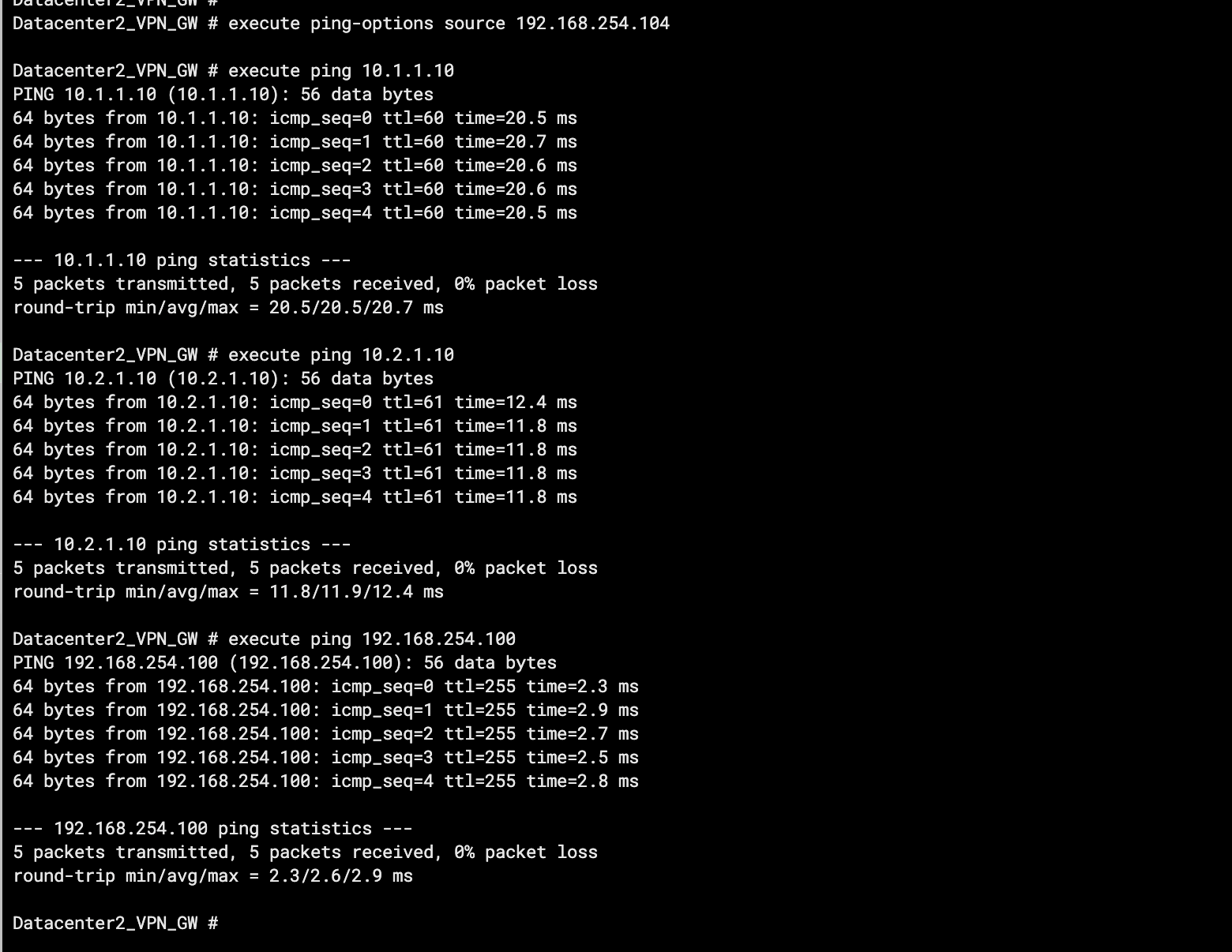
Test the connectivity between IDC1 and service VPC1, service VPC2, and IDC2.
Log on to the CLI of the client in IDC1.
Run the ping command on the client to access ECS1 in service VPC1, ECS1 in service VPC2, and the client in IDC2.
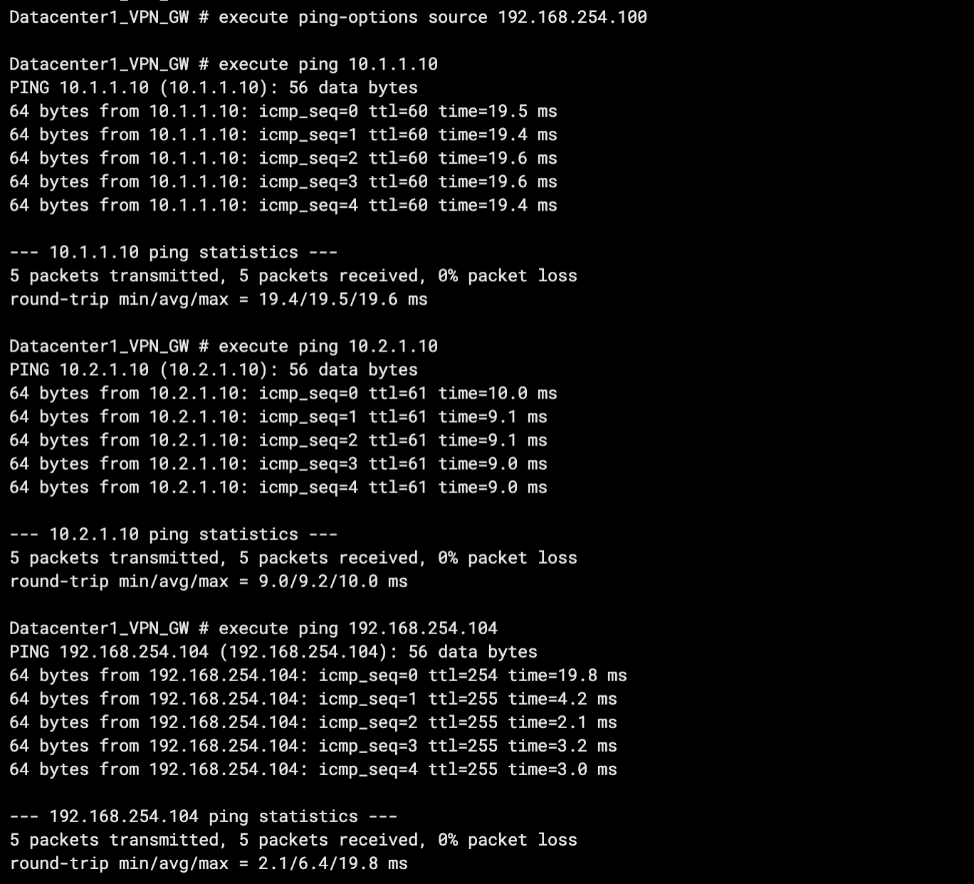 As shown in the preceding figure, if the client in IDC1 receives a response message, it indicates that IDC1 can access resources in service VPC1, service VPC2, and IDC2.
Test the connectivity between IDC2 and service VPC1, service VPC2, and IDC1.
Log on to the CLI of the client in IDC2.
Run the ping command on the client to access ECS1 in service VPC1, ECS1 in service VPC2, and the client in IDC1.
 As shown in the preceding figure, if the client in IDC2 receives a response message, it indicates that IDC2 can access resources in service VPC1, service VPC2, and IDC1.
Test the connectivity between service VPC1 and IDC1, and between service VPC1 and IDC2.
Log on to the ECS1 instance in service VPC1. For more information, see ECS remote connection guide.
Run the ping command on the ECS1 instance to access the clients in IDC1 and IDC2.
ping <IP address of the client in the data center>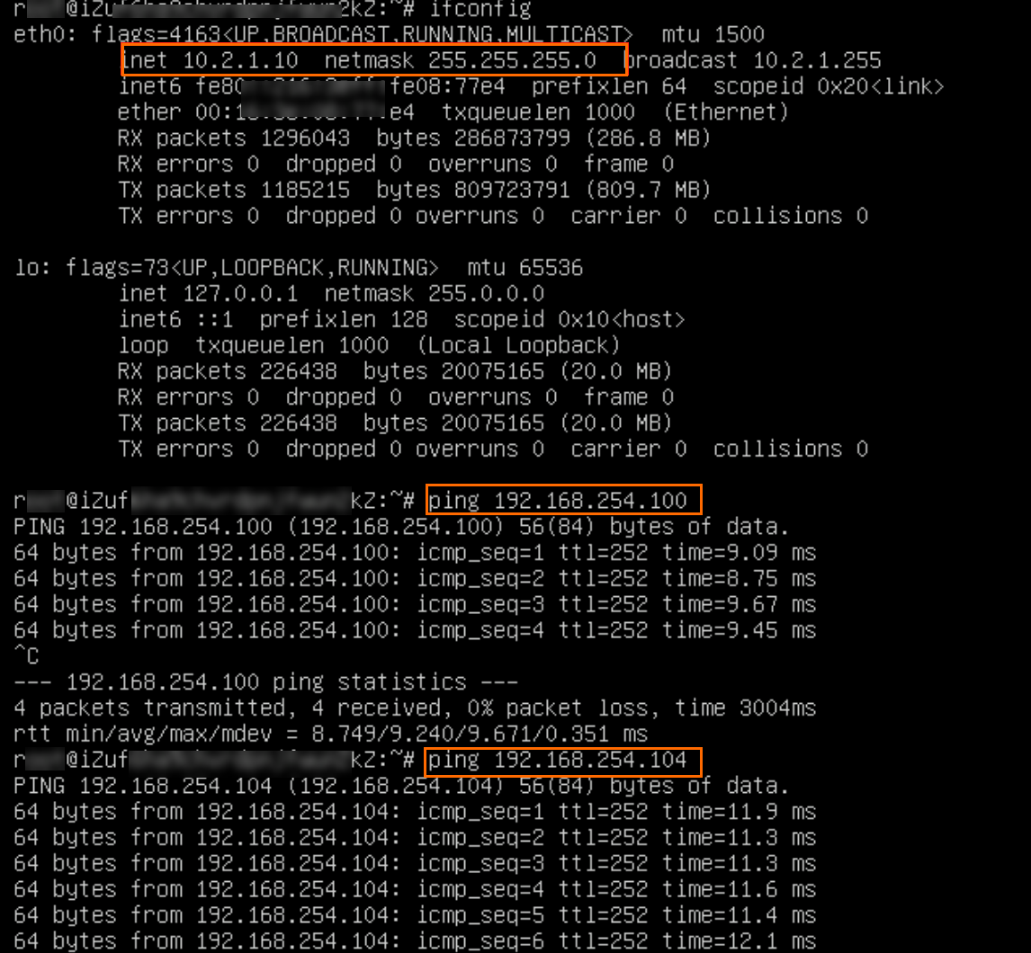
As shown in the preceding figure, if the ECS1 instance receives a response message, it indicates that service VPC1 can access resources in IDC1 and IDC2.
Test the connectivity between service VPC2 and IDC1, and between service VPC2 and IDC2.
Log on to the ECS1 instance in service VPC2. For more information, see ECS remote connection guide.
Run the ping command on the ECS1 instance to access the clients in IDC1 and IDC2.
ping <IP address of the client in the data center>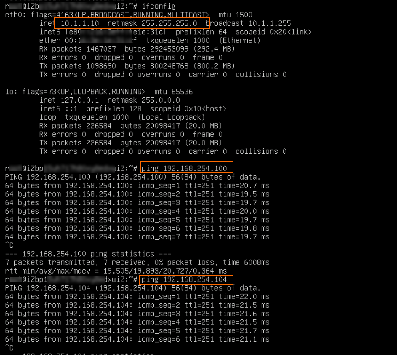
As shown in the preceding figure, if the ECS1 instance receives a response message, it indicates that service VPC2 can access resources in IDC1 and IDC2.
Test the connectivity between service VPC1 and service VPC2.
Log on to the ECS1 instance in service VPC1. For more information, see ECS remote connection guide.
Run the ping command on the ECS1 instance to access the ECS1 instance in service VPC2.
ping <IP address of the ECS instance>
As shown in the preceding figure, if the ECS1 instance in service VPC1 receives a response message, it indicates that service VPC1 can access resources in service VPC2.
Log on to the ECS1 instance in service VPC2. For more information, see ECS remote connection guide.
Run the ping command on the ECS1 instance to access the ECS1 instance in service VPC1.
ping <IP address of the ECS instance>
As shown in the preceding figure, if the ECS1 instance in service VPC2 receives a response message, it indicates that service VPC2 can access resources in service VPC1.