By SIG for High Performance Networking

In the previous article, " SMC-R Interpretation Series – Part 1: Transparently Improve TCP Application Network Performance on the Cloud", we learned that compared to TCP, RDMA can bypass software protocol stack and offload network transmission to hardware. This feature can increase network bandwidth and reduce network latency and CPU load. And SMC-R is further compatible with the socket interface while providing RDMA services, which can improve network performance for TCP applications transparently. Therefore, the high-performance network SIG in OpenAnolis believes that SMC-R will become an important component of the next-generation data center kernel protoco and has made a lot of optimizations, feeding back to the upstream Linux community.
As the second article in the SMC-R series, we will focus on the complete SMC-R communication process. Through the specific process of connection, transmission, and destruction, readers can realize that SMC-R is a hybrid solution that combines generic TCP and high-performance RDMA.
As mentioned in the previous article, there are two ways to use SMC-R protocols. One is to explicitly create the AF_SMC socket in the application. The second is to transparently replace the AF_INET socket in the application with the AF_SMC socket by using LD_PRELOAD or ULP + eBPF. By default, the node using SMC-R communication has loaded the SMC kernel module and run the application on the SMC-R protocol in the above way.
Next, we take the first contact (the first connection between the two ends of the communication) scenario as an example to introduce the SMC-R communication process.
When using SMC-R communication, we first need to confirm whether the peer supports the SMC-R protocol. Therefore, when the SMC-R protocol stack creates an SMC socket for the application, it creates and maintains a TCP socket (clcsock) associated with it in the kernel, and establishes a TCP connection with the peer based on the clcsock.
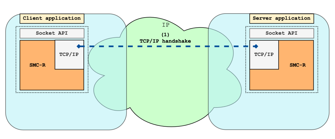
(Figure 1. TCP handshake confirms peer SMC-R capability)
In the TCP connection three-way handshake, the SYN/ACK sent by one end of the SMC-R protocol carries a special TCP option (Kind = 254, Magic Number=0xe2d4) to indicate that it supports SMC-R. By checking the SYN/ACK sent by the peer, the communication node learns Peer's SMC-R capability and then decides whether to continue using SMC-R communication.

(Figure 2. Three-way handshake carrying special TCP option [1])

(Figure 3. TCP options that represent SMC-R)
If one of the two ends of the communication indicates that SMC-R is unable to be supported during the preceding TCP handshake, the protocol fallback process is triggered.
When performing protocol fallback, the socket corresponding to fd held by application will be replaced from smc socket to clcsock. Then, the application will use TCP protocol to communicate, thus ensuring that the data transmission will not be interrupted due to protocol compatibility issues.
It should be noted that the protocol fallback only occurs during the communication negotiation process, such as the TCP handshake mentioned before, or the SMC-R connection establishment process mentioned below. To facilitate tracking and diagnosis, the SMC-R protocol classifies the potential fallback reasons. Through the userspace utilities smc-tools, users can observe the protocol fallback events and causes.

(Figure 4. Observe fallback through smc-tools)
If both ends support SMC-R in the TCP handshake, a SMC-R connection will be established. The establishment of SMC-R connections depends on TCP connections to pass control messages, which are called Connection Layer Control (CLC) messages.
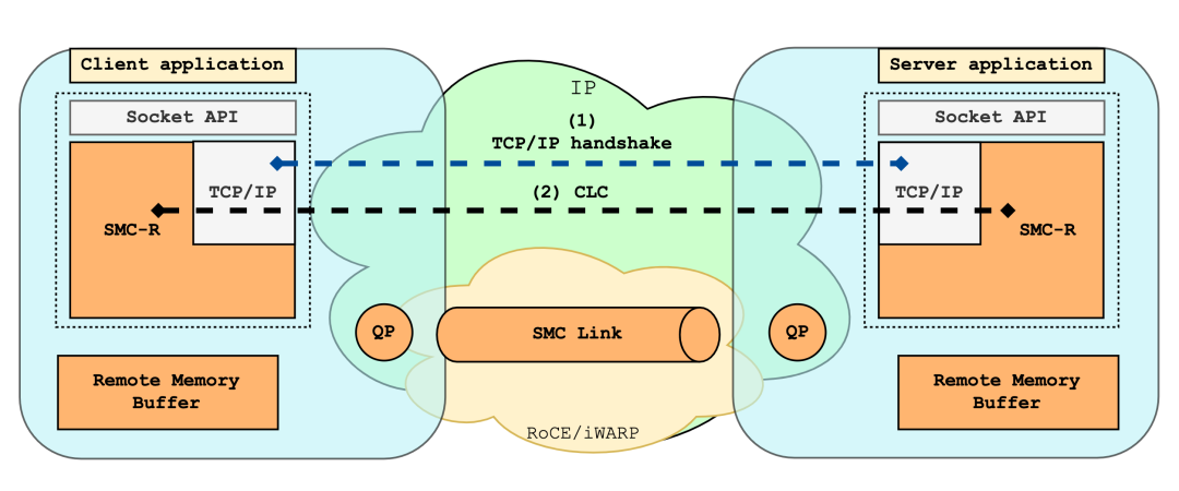
(Figure 5. Use CLC messages to establish an SMC-R connection)
The main responsibility of CLC messages is to synchronize information such as RDMA resources and shared memory at both ends. The process of establishing an SMC-R connection is similar to that of an SSL handshake, which includes Proposal, Accept, Decline, and Confirm. During the connection establishment process, if an unrecoverable exception (such as RDMA resource invalid) occurs, the protocol fallback process will also be triggered.

(Figure 6. SMC-R handshake process [1])
Specially, in the 'first contact' scenario, there is no available RDMA resources between the two ends. Therefore, when the first SMC-R connection is established, RDMA resources required for SMC-R communication such as QPs and shared memory, will be applied.
At the initial stage of SMC-R connection establishment, both ends find available RDMA devices and create necessary RDMA resources based on the found devices, including Queue Pair (QP), Completion Queue (CQ), Memory Region (MR), Protect Domain (PD).
Among them, QP and CQ are the basis of RDMA communication and provide an asynchronous communication mechanism between RDMA users (such as SMC kernel protocol stack) and RDMA devices (RNIC).
QP is essentially a Work Queue (WQ) that stores Work Request (WR). The WQ responsible for sending is called Send Queue (SQ), and the WQ responsible for receiving is called Receive Queue (RQ). The two always appear in pairs and are called QP. The user packages the tasks that are required for RNIC to complete as a Work Queue Element (WQE) and posts them to the QP. The RNIC takes the WQE out of the QP and completes the tasks.
CQ is essentially a queue that stores Work Completion (WC). After the RNIC completes the WR, the completion information is packaged as a Completion Queue Element (CQE) into the CQ. The user polled CQE from the CQ and learned that the RNIC has completed a certain WR.
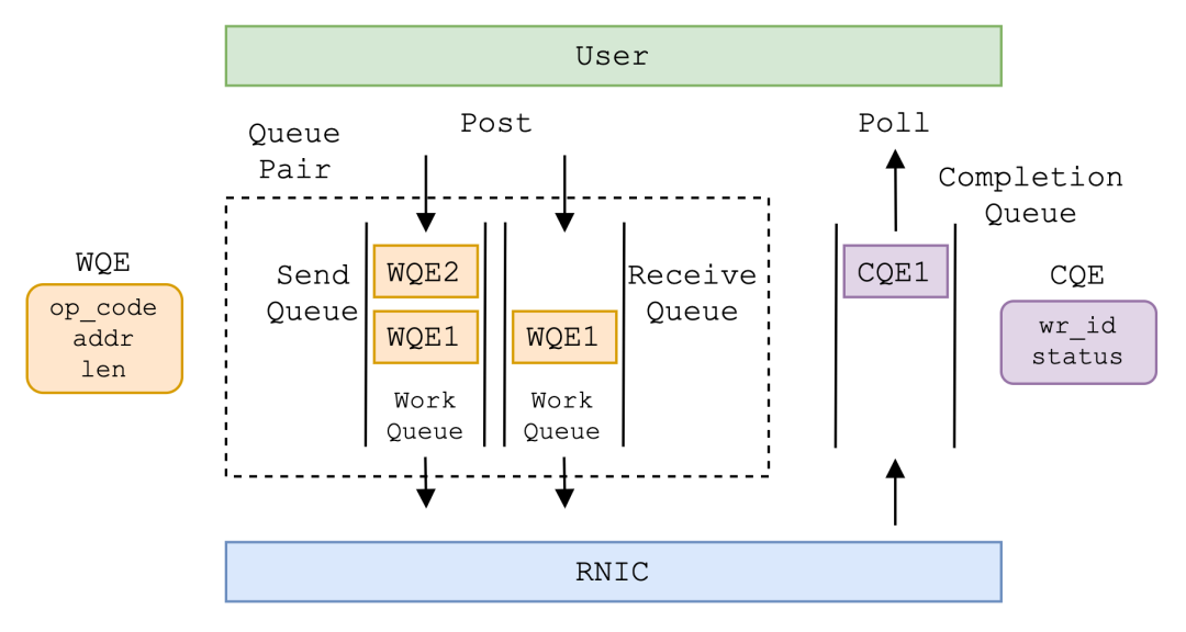
(Figure 7. RDMA work queue)
The two ends of the communication synchronize the created RDMA resources to the peer through CLC messages, thus establishing an RDMA link based on RC (Reliable Connection) QP between the two ends. In SMC-R, this point-to-point logical RDMA link is called an SMC-R Link. An SMC-R Link carries data traffic from multiple SMC-R connections.
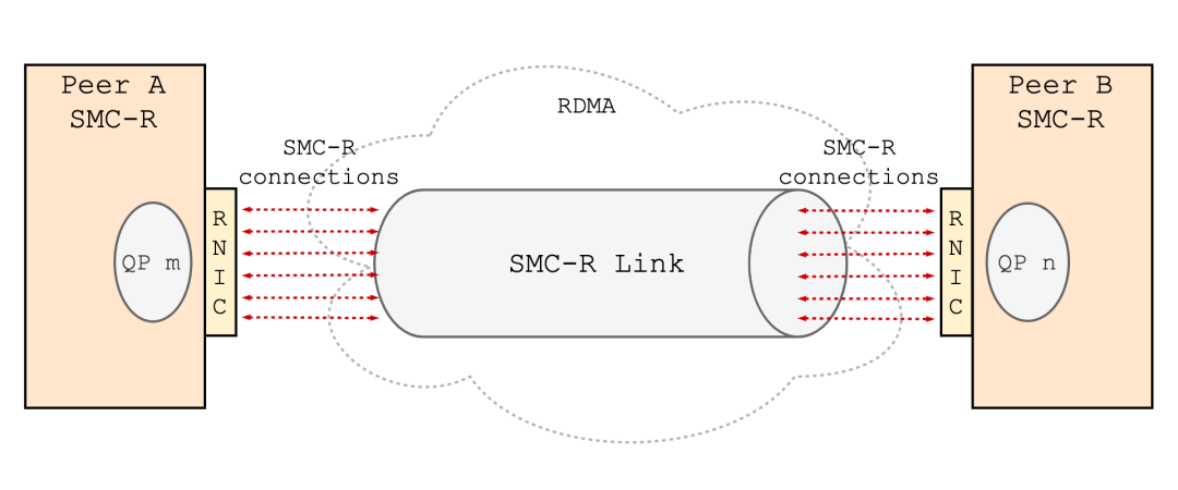
(Figure 8. SMC Link)
Multiple pairs of RNICs between communication nodes result in multiple links. These Links logically form a group, which is called an SMC-R Link Group.
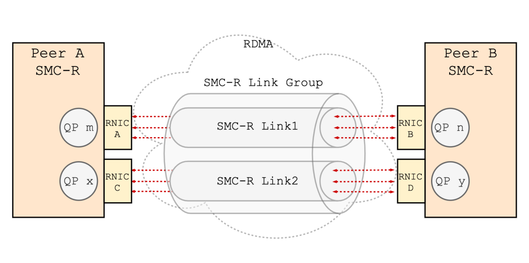
(Figure 9. SMC-R Link Group)
In the Linux implementation, each Link Group has 1-3 Links and can host up to 255 SMC-R connections. These connections are evenly associated with a Link of the Link Group. The data sent by the application over the SMC-R connection will be transmitted by the associated Link (RDMA Link).
In the same Link Group, all Links are "equal" to each other. This "equality" is reflected in the fact that Links in the same Link Group have the right to access all send and receive buffers (sndbuf and RMB mentioned below) of SMC-R connection in the group, and can carry any SMC-R connection data streams. Therefore, when a Link is invalid (such as RNIC down), all connections associated with this Link can be migrated to another Link of the same Link Group. This makes SMC-R communication stable and reliable and has certain disaster recovery capabilities.
In SMC-R, the Link (Group) is created at first contact and destroyed after the last SMC-R connection is disconnected for a while (10 mins in the Linux implementation). It has a longer life cycle than the connection. SMC-R connections created after the first contact will try to reuse the existing Link (Group). This design makes full use of existing RDMA resources and avoids the additional overhead caused by frequent creation and destruction.
The SMC-R protocol stack allocates a separate send and receive buffer for each SMC-R connection: sndbuf (send buffer) and RMB (Remote Memory Buffer, receive buffer). They are two contiguous ring buffers and 16KB to 512KB in size.
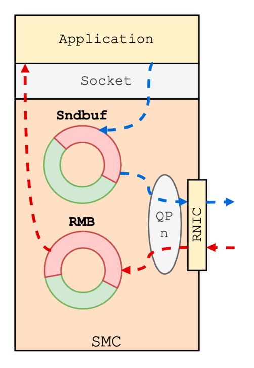
(Figure 10. SMC-R connection ring buffer)
Among them, sndbuf is used to store the data to be sent by the connection and is registered as DMA memory. The local RNIC device can directly access sndbuf and take the payload from it. The RMB is used to store the data written by the remote node RNIC. Since it needs to be accessed by the remote node, RMB is registered as RDMA memory.
The process of registering RDMA memory is called Memory Registration. It mainly performs the following operations:
After the SMC-R connection is destroyed, the corresponding sndbuf and RMB will be reclaimed to the memory pool maintained by Link Group for subsequent reuse by new connections. This reduces the impact of RDMA memory creation/destruction on connection establishment performance.
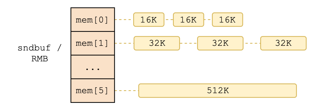
(Figure 11. sndbuf / RMB memory pool)
In the first contact scenario, the newly established SMC-R Link has not been verified. Therefore, before the Link is officially used to transmit application data, both ends of the communication send a Link Layer Control (LLC) message based on the Link to check whether the Link is available.
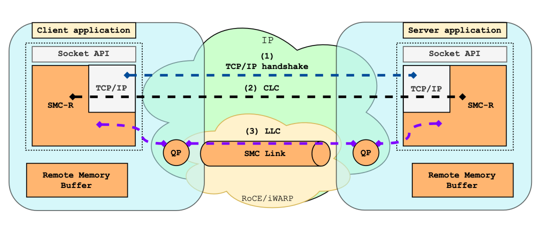
(Figure 12. Use LLC messages to confirm the availability of SMC Link)
LLC messages are usually in request-response mode and are used to transmit control information at the Link level, such as adding /deleting /confirming Links, confirming /deleting r_key.

(Figure 13. LLC message request-response mode)
| Category | Description |
| ADD_LINK | Add a new Link to the Link Group. |
| CONFIRM_LINK | Check whether the newly created Link can work properly. |
| DELETE_LINK | Delete a specific Link or an entire Link Group. |
| CONFIRM_RKEY | Notify the Link peer when adding RMB. |
| DELETE_RKEY | Notify the Link peer when one or more RMB is deleted. |
| TEST_LINK | Check whether the Link is healthy and active. |
(Table/ Typical LLC message meaning)
The transmission of LLC messages is completed based on the SEND operation of RDMA, as opposed to the RDMA WRITE operation mentioned later.
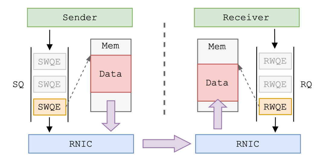
(Figure 14. SEND operation)
SEND operation is also called "bilateral operation" since it requires both ends of the communication to participate. The transmission process of a SEND is:
By sending and receiving LLC messages of the CONFIRM_LINK type on the Link, both ends of the communication confirm that the newly created Link has the capability of RDMA communication and can be used to transmit data.
Through the preceding steps, the SMC-R connection in the first contact scenario finally ended. Then, the application will transfer data through an established SMC-R connection.
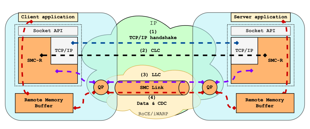
(Figure 15. Communication based on RDMA shared memory)
The data sent by the application to the SMC-R connection is written to the remote node RMB by the associated Link through RDMA WRITE operation.
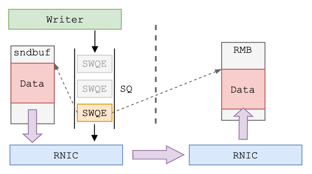
(Figure 16. RDMA WRITE operations)
Unlike the SEND operation mentioned before, RDMA WRITE is called a "unilateral operation". This is because only the end that initiated RDMA WRITE participates in the data transmission, and the RDMA user on the receiving end does not participate and is not aware of the arrival of the data. The following is the procedure of an RDMA WRITE operation:
Since RDMA WRITE does not require the participation of the RDMA users of receiver, it is ideal for the direct writing of large amounts of data. However, since the receiver is not aware of the arrival of the data, the sender needs to send a control message to notify the receiver through the SEND operation after writing the data. In SMC-R, this control message is called a Connection Data Control (CDC) message. CDC messages contain RMB-related control information to synchronize data read and write.
| Content | Meaning |
| Sequence number | CDC message serial number |
| Alert token | The SMC-R connection ID that sent this message |
| Producer cursor | RMB data production cursor (Updated by the writer) |
| Producer cursor wrap seqno | The times of RMB data producing wrap (Updated by the writer) |
| Consumer cursor wrap seqno | The times of RMB data consuming wrap (Updated by readers) |
| Consumer cursor | RMB data consuming cursor (Updated by readers) |
(Table/ CDC messages)
In the first article of the series, we mentioned that "shared memory" in the SMC-R refers to RMB on the receiver. Combined with the preceding RDMA WRITE operations and CDC messages, the SMC-R shared memory communication process can be summarized as follows:
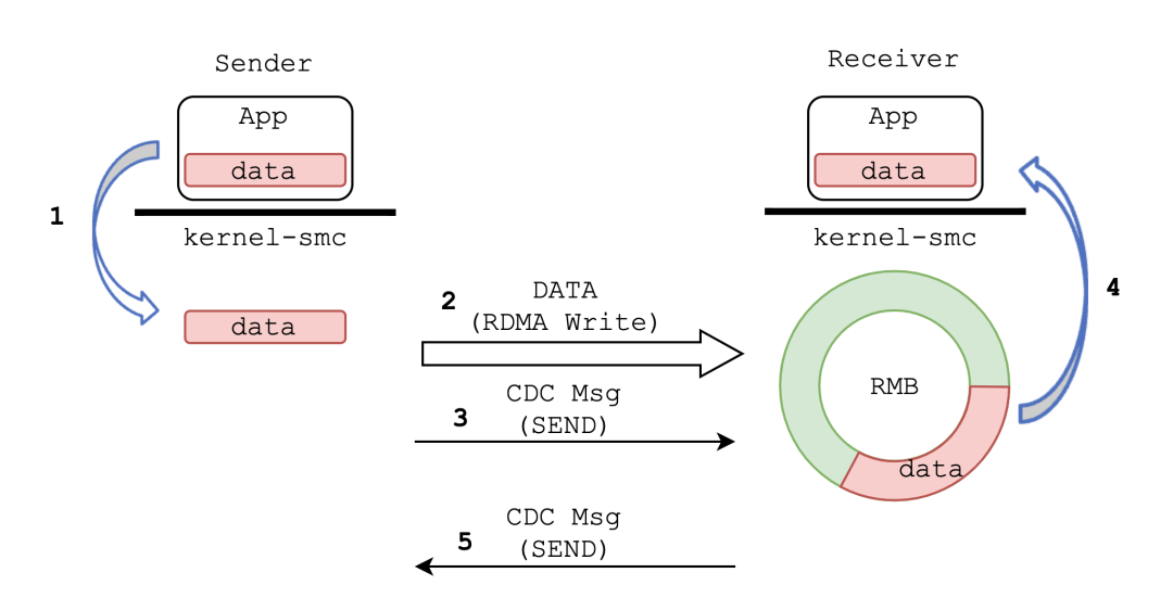
(Figure 17. Shared memory communication details)
After the data transmission is completed, the SMC-R connection closing process will be initiated. Similar to TCP, SMC-R connections also have a semi-closed/ closed state. The disconnected SMC-R connection is unbound from the Link (Group). The related sndbuf and RMB are also reclaimed to the memory pool for reuse. At the same time, the TCP connection associated with the SMC-R connection also enters the closing process and is finally released.
If there is no connection in the Link (Group), the Link (Group) will also enter the destruction process after waiting for a while (10 mins in Linux implementation). Destroying Link (Group) will release all RDMA resources related to it, including QP, CQ, PD, MR, and all sndbuf and RMB.
In this article, we took the first contact scenario as an example to introduce the complete SMC-R communication process. The process includes: confirming the peer's SMC-R capability through TCP handshake; using TCP connection to transfer CLC messages, exchanging RDMA resources, creating RDMA links, and establishing SMC-R connections; sending LLC messages through RDMA SEND operation to verify Link availability; transmitting data by RDMA WRITE based on Link; closing SMC-R and TCP connections and destroy RDMA resources.
These processes reflect the "hybrid" feature of SMC-R. SMC-R not only takes advantage of the generality of TCP, such as confirming the peer capability through TCP connection but also takes advantage of the high performance of RDMA, such as transmitting application data traffic through Link. Therefore, SMC-R can provide TCP applications with transparent and senseless network performance improvement while being compatible with the key functions of the existing TCP/IP ecosystem.
Faster Container Image Loading Speed with Nydus, RAFS, and EROFS
A Tribute to Hackers: The Way to Explore Memory Virtualization

96 posts | 6 followers
FollowOpenAnolis - May 13, 2022
OpenAnolis - July 14, 2022
OpenAnolis - June 26, 2023
OpenAnolis - March 7, 2022
Alibaba Cloud Community - July 15, 2022
ApsaraDB - December 25, 2023

96 posts | 6 followers
Follow Elastic High Performance Computing Solution
High Performance Computing (HPC) and AI technology helps scientific research institutions to perform viral gene sequencing, conduct new drug research and development, and shorten the research and development cycle.
Learn More Elastic High Performance Computing
A HPCaaS cloud platform providing an all-in-one high-performance public computing service
Learn More Remote Rendering Solution
Connect your on-premises render farm to the cloud with Alibaba Cloud Elastic High Performance Computing (E-HPC) power and continue business success in a post-pandemic world
Learn More Networking Overview
Connect your business globally with our stable network anytime anywhere.
Learn MoreMore Posts by OpenAnolis