
By Li Licheng (Changbao)
Today's 3D rendering engines for games and multimedia are daunting in terms of mathematical and programming complexity. From the programming interface OpenGL to the breathtakingly realistic UE5 (Unreal Engine 5), the size of the latter engine alone (without debugging) is nearly 40 GB (UE5 does not only have the function of rendering). The two core technologies in UE5, Nanite (a virtual micro-polygon geometry technology) and Lumen (a dynamic global illumination technology), are even more complicated.
It may be difficult for developers working on non-rendering engine-related tasks to build the simplest 3D programs, but this is not the case. This article practices basic 3D rendering techniques such as orthogonal projection, simple triangle rasterization, z-buffer (depth buffer), and flat shading in 200+ lines of pure Java code. Then, we will focus on ray tracing in the next article.
The 3D rendering engine finally implemented in this article is very simple, without any algorithm optimization. Only the CPU is used, whose actual performance is far inferior to OpenGl. However, its purpose is to help us understand how modern engines apply their magic so we can use them better.
Trigonometric functions, matrix operations, vector operations, and normal vectors.
If you haven't learned or forgotten the knowledge above, don't worry. This article gives a simple explanation with examples. At the same time, you don't have to worry too much about mathematical knowledge but using it properly is the purpose.
Of course, if you are familiar with the knowledge above, it will be easier to read.
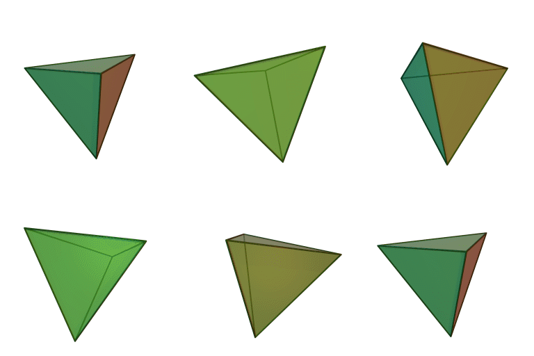
We will draw a tetrahedron because it is the simplest 3D figure.
It is used to display graphics:
public static void main(String[] args) {
        JFrame frame = new JFrame();
        Container pane = frame.getContentPane();
        pane.setLayout(new BorderLayout());

        // panel to display render results
        JPanel renderPanel = new JPanel() {
            public void paintComponent(Graphics g) {
                Graphics2D g2 = (Graphics2D) g;
                g2.setColor(Color.BLACK);
                g2.fillRect(0, 0, getWidth(), getHeight());

                // rendering magic will happen here
            }
        };
        pane.add(renderPanel, BorderLayout.CENTER);

        frame.setSize(600, 600);
        frame.setVisible(true);
}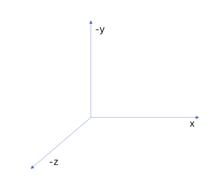
Now, let's add some basic model classes for the 3D world: vertices and triangles. A vertex is just a simple structure to store our three coordinates (x, y, and z), while a triangle binds three vertices together and stores their color.
// x indicates the movement in the left and right directions
// y indicates the up-and-down movement on the screen
// z indicates depth (so the z axis is perpendicular to your screen). Positive z means "towards the observer".
class Vertex {
    double x;
    double y;
    double z;
    Vertex(double x, double y, double z) {
        this.x = x;
        this.y = y;
        this.z = z;
    }
}

class Triangle {
    Vertex v1;
    Vertex v2;
    Vertex v3;
    Color color;
    Triangle(Vertex v1, Vertex v2, Vertex v3, Color color) {
        this.v1 = v1;
        this.v2 = v2;
        this.v3 = v3;
        this.color = color;
    }
}
Why do we use triangles to describe the 3D world?
It is very simple. The target 3D graphics is a combination of four triangles (put them on the list first). At the same time, give them different colors to distinguish them.
List tris = new ArrayList<>();
tris.add(new Triangle(new Vertex(100, 100, 100),
                      new Vertex(-100, -100, 100),
                      new Vertex(-100, 100, -100),
                      Color.WHITE));
tris.add(new Triangle(new Vertex(100, 100, 100),
                      new Vertex(-100, -100, 100),
                      new Vertex(100, -100, -100),
                      Color.RED));
tris.add(new Triangle(new Vertex(-100, 100, -100),
                      new Vertex(100, -100, -100),
                      new Vertex(100, 100, 100),
                      Color.GREEN));
tris.add(new Triangle(new Vertex(-100, 100, -100),
                      new Vertex(100, -100, -100),
                      new Vertex(-100, -100, 100),
                      Color.BLUE));
Now, place them in the previous panel, but only display the frame lines. Since the orthogonal projection is adopted, the construction process is very simple. Just ignore the z axis and draw the line.
The frame line is only used to see the tetrahedron intuitively at the moment. This 2dAPI will not be used in the final rendering.
// The generated shape is centered on the origin (0, 0, 0), and we will do rotation around the origin later.
g2.translate(getWidth() / 2, getHeight() / 2);
g2.setColor(Color.WHITE);
for (Triangle t : tris) {
    Path2D path = new Path2D.Double();
    path.moveTo(t.v1.x, t.v1.y);
    path.lineTo(t.v2.x, t.v2.y);
    path.lineTo(t.v3.x, t.v3.y);
    path.closePath();
    g2.draw(path);
}
We will get the following result:
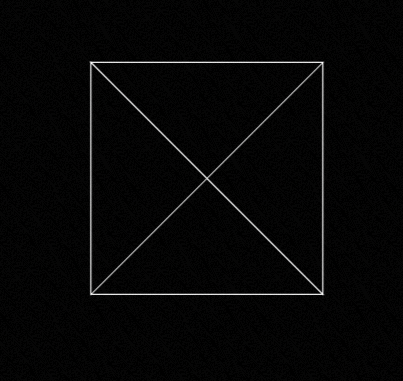
This is our tetrahedron. Let's add some rotation to it.
There are many ways to deal with 3D points, but the most flexible one is to use matrix multiplication. The point is represented as a 3 x 1 vector. Then, the transformation is simply multiplying the 3 x 1 vector by a 3 x 3 matrix.

For example, double zoom:

Of course, the focus is on rotation. Any rotation in 3D space can be represented as a combination of 3 original rotations: xy plane rotation, yz plane rotation, and xz plane rotation. We can write the transformation matrix for each rotation:

At the same time, matrix transformation has such characteristics:

Multiple matrix transformations can be merged into one in advance.
Take a look at how the multiplication between matrices and matrices is implemented through code:
class Matrix3 {
    double[] values;
    Matrix3(double[] values) {
        this.values = values;
    }
    Matrix3 multiply(Matrix3 other) {
        double[] result = new double[9];
        for (int row = 0; row < 3; row++) {
            for (int col = 0; col < 3; col++) {
                for (int i = 0; i < 3; i++) {
                    result[row * 3 + col] +=
                        this.values[row * 3 + i] * other.values[i * 3 + col];
                }
            }
        }
        return new Matrix3(result);
    }
    Vertex transform(Vertex in) {
        return new Vertex(
            in.x * values[0] + in.y * values[3] + in.z * values[6],
            in.x * values[1] + in.y * values[4] + in.z * values[7],
            in.x * values[2] + in.y * values[5] + in.z * values[8]
        );
    }
}
Rotate xz plane (y axis is used to distinguish left and right) and yz plane (x axis is used to distinguish up and down):
double heading = Math.toRadians(x[0]);
                Matrix3 headingTransform = new Matrix3(new double[]{
                        Math.cos(heading), 0, -Math.sin(heading),
                        0, 1, 0,
                        Math.sin(heading), 0, Math.cos(heading)
                });
double pitch = Math.toRadians(y[0]);
                Matrix3 pitchTransform = new Matrix3(new double[]{
                        1, 0, 0,
                        0, Math.cos(pitch), Math.sin(pitch),
                        0, -Math.sin(pitch), Math.cos(pitch)
                })
// Merge matrices in advance
Matrix3 transform = headingTransform.multiply(pitchTransform);
Then, change the angles represented by x and y by listening to the motion of the mouse:
renderPanel.addMouseMotionListener(new MouseMotionListener() {
            @Override
            public void mouseDragged(MouseEvent e) {
                double yi = 180.0 / renderPanel.getHeight();
                double xi = 180.0 / renderPanel.getWidth();
                x[0] = (int) (e.getX() * xi);
                y[0] = -(int) (e.getY() * yi);
                renderPanel.repaint();
            }

            @Override
            public void mouseMoved(MouseEvent e) {

            }
        });
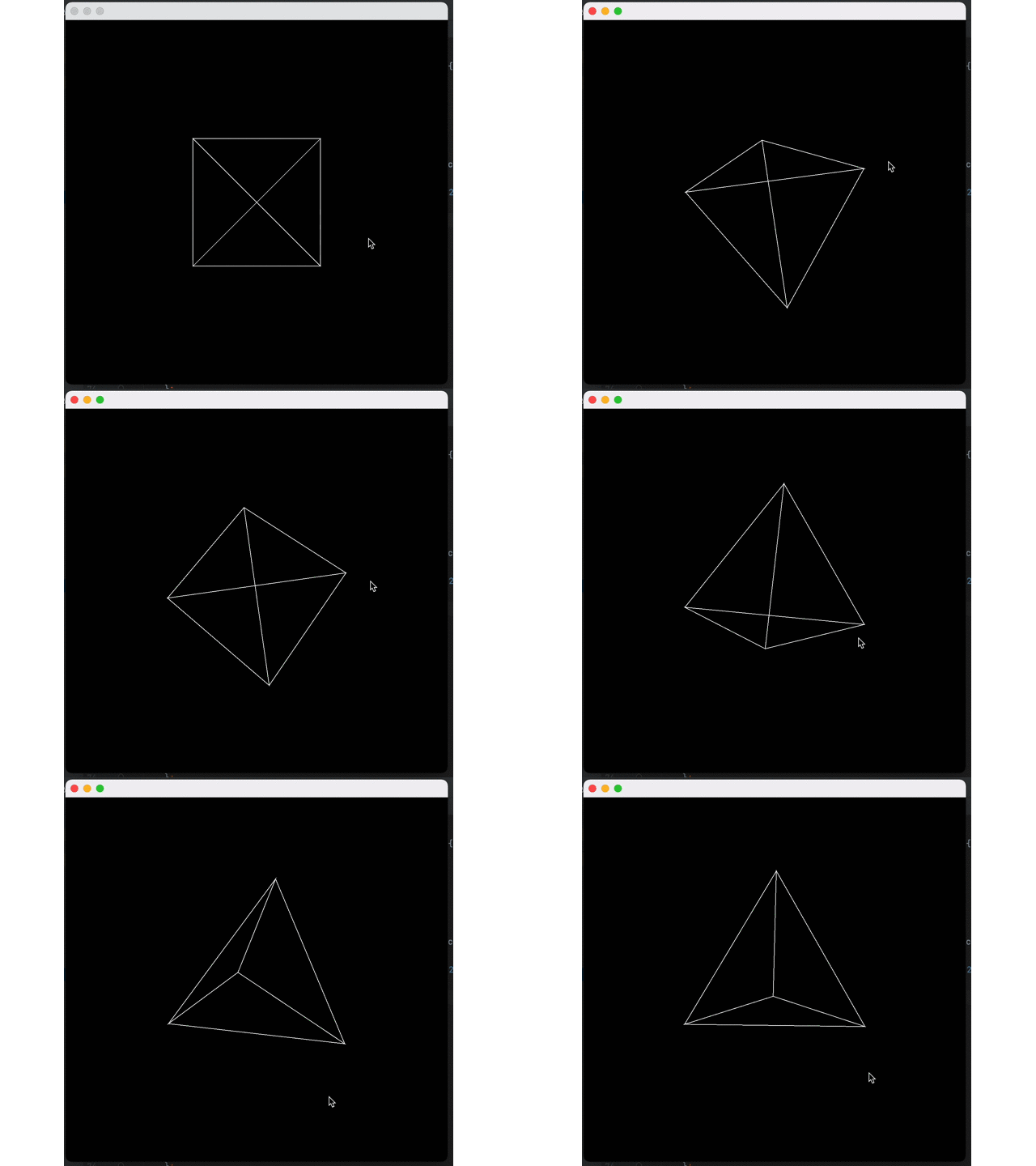
Now, we can rotate the previous tetrahedron:
g2.translate(getWidth() / 2, getHeight() / 2);
g2.setColor(Color.WHITE);
for (Triangle t : tris) {
    Vertex v1 = transform.transform(t.v1);
    Vertex v2 = transform.transform(t.v2);
    Vertex v3 = transform.transform(t.v3);
    Path2D path = new Path2D.Double();
    path.moveTo(v1.x, v1.y);
    path.lineTo(v2.x, v2.y);
    path.lineTo(v3.x, v3.y);
    path.closePath();
    g2.draw(path);
}
Effect:
Now, we need to fill these triangles with some substance. First, we need to rasterize these triangles: convert them into a list of pixels they occupy on the screen.
The term rasterization often appears in computer graphics. Many related books have given their definitions. However, currently, I think a more accurate definition is:
”Rasterization is a process of drawing onto the screen. A literary explanation goes: rasterization solidifies life.”
One of the most important concepts in rasterization is to judge the relationship between a pixel and a triangle. More precisely, we need to consider the positional relationship between the center point of the pixel and the triangle.
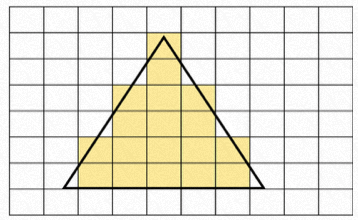
There are many mathematical ways to judge whether a point is inside a triangle. This article chooses the cross product method. (Since orthogonal projection is adopted, this method will make the construction process easier.) If you are interested in other methods, you can try them according to their mathematical principles.
The direction of the cross product is orthogonal to the two initial vectors. This direction can be determined by the right-hand rule. We can use our right hand to determine the direction of the cross product of vector a to vector b. We will find that the direction is facing up (Figure 1), and the direction of the cross product of vector b to vector a is facing down by the right-hand rule, which is why a x b = -b x a.
The cross multiplication formula of the vector:
(x1,y1,z1)X(x2,y2,z2)=(y1z2-y2z1, z1x2-z2y1, x1y2-x2y1)
As mentioned earlier, we can judge whether a point is in a triangle by cross product, for example (Figure 2):
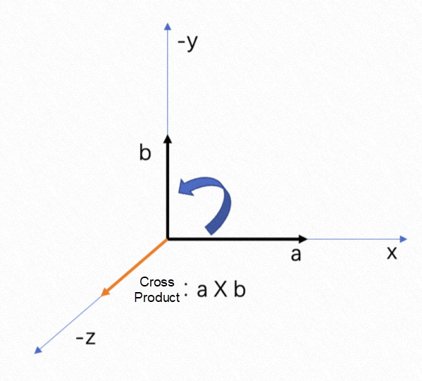
Figure 1
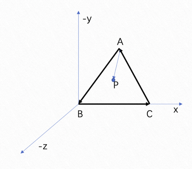
Figure 2
The direction of the triangle is counterclockwise, and the cross product direction from the vector AB to the vector AP is -z, indicating that point P is on the left side of AB. The cross product direction from the vector BC to the vector BP is -z, indicating that point P is on the left side of BC. The cross product direction from the vector CA to the vector CP is -z, indicating that point P is on the left side of AC. This means point P is inside the triangle. Since if it is not inside the triangle, there is at least one side that indicates point P is on the right (point P is also on the right side of the triangle's three sides if the triangle is clockwise. We only need to ensure that point P is always on the left or right side of the three sides to say it is inside the triangle).
Note: Here, since orthogonal projection is adopted, we only consider whether the pixels on the projection plane (xy plane) are within the projection triangle of the space triangle on this plane, which means z can be regarded as 0.
Code:
    static boolean sameSide(Vertex A, Vertex B, Vertex C, Vertex p){
        Vertex V1V2 = new Vertex(B.x - A.x,B.y - A.y,B.z - A.z);
        Vertex V1V3 = new Vertex(C.x - A.x,C.y - A.y,C.z - A.z);
        Vertex V1P = new Vertex(p.x - A.x,p.y - A.y,p.z - A.z);

        // If the cross product of vector V1V2 and vector V1V3 is the same as the one of vector V1V2 and vector V1p, they are on the same side.
        // We only need to judge the direction of z
        double V1V2CrossV1V3 = V1V2.x * V1V3.y - V1V3.x * V1V2.y;
        double V1V2CrossP = V1V2.x * V1P.y - V1P.x * V1V2.y;

        return V1V2CrossV1V3 * V1V2CrossP >= 0;
}Now, we can know whether a pixel needs to be rendered. What we have to do now is to traverse all the pixels in the range to determine whether they need to be rendered.
Complete our code:
                for (Triangle t : tris) {
                    Vertex v1 = transform.transform(t.v1);
                    Vertex v2 = transform.transform(t.v2);
                    Vertex v3 = transform.transform(t.v3);
                    v1.x += getWidth() / 2.0;
                    v1.y += getHeight() / 2.0;
                    v2.x += getWidth() / 2.0;
                    v2.y += getHeight() / 2.0;
                    v3.x += getWidth() / 2.0;
                    v3.y += getHeight() / 2.0;
                    // Calculate the range to be processed
                    int minX = (int) Math.max(0, Math.ceil(Math.min(v1.x, Math.min(v2.x, v3.x))));
                    int maxX = (int) Math.min(img.getWidth() - 1,
                            Math.floor(Math.max(v1.x, Math.max(v2.x, v3.x))));
                    int minY = (int) Math.max(0, Math.ceil(Math.min(v1.y, Math.min(v2.y, v3.y))));
                    int maxY = (int) Math.min(img.getHeight() - 1,
                            Math.floor(Math.max(v1.y, Math.max(v2.y, v3.y))));

                    for (int y = minY; y < = maxY; y++) {
                        for (int x = minX; x < = maxX; x++) {
                            Vertex p = new Vertex(x,y,0);
                            // Judge once for each vertex
                            boolean V1 = sameSide(v1,v2,v3,p);
                            boolean V2 = sameSide(v2,v3,v1,p);
                            boolean V3 = sameSide(v3,v1,v2,p);
                            if (V3 && V2 && V1) {
                                img.setRGB(x, y, t.color.getRGB());
                            }
                        }
                    }
                }

                g2.drawImage(img, 0, 0, null);
Let's see the actual effect!
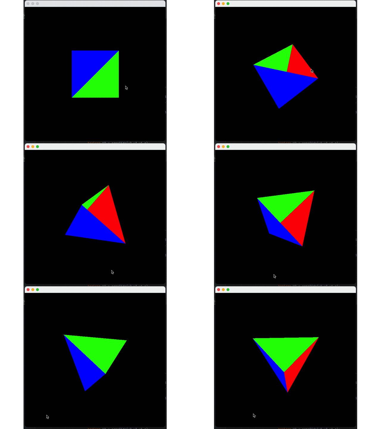
I believe you have found the problem: the blue triangle is always above others. This happens because we are currently drawing triangles one by one. The blue triangle is the last, so it is drawn on top of the other triangles.
This leads to the next concept: the concept of z-buffer (depth buffer).
Its function is to build an intermediate array during rasterization, which will store the depth of the last element seen at any given pixel. When rasterizing the triangle, we will check whether the pixel depth is lower than what we saw before (because the forward direction is -z), and only color it when the pixel is higher than others.
double[] zBuffer = new double[img.getWidth() * img.getHeight()];
// initialize array with extremely far away depths
for (int q = 0; q < zBuffer.length; q++) {
    zBuffer[q] = Double.NEGATIVE_INFINITY;
}

for (Triangle t : tris) {
// The previous code
    if (V3 && V2 && V1) {
    double depth = v1.z + v2.z + v3.z;
    int zIndex = y * img.getWidth() + x;
    if (zBuffer[zIndex] < depth) {
      img.setRGB(x, y, t.color.getRGB());
      zBuffer[zIndex] = depth;
      }
    }
}
Effect:
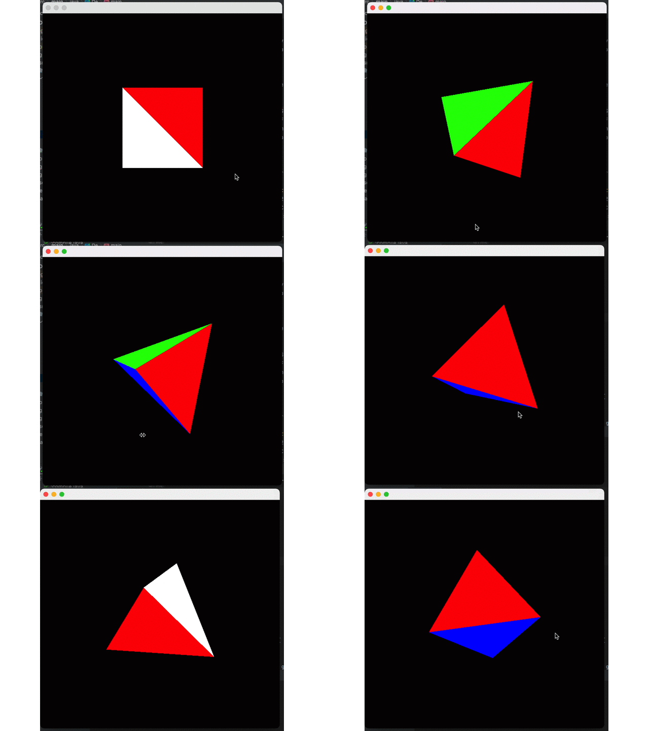
So far, the rendering pipeline looks normal, but there is still an important effect missing: shadows.
The shadow in computer graphics can be simply explained as changing the color of the surface according to the angle of the surface and the distance from the light.
The simplest form of coloring is flat shading. It only considers the angle between the surface normal and the direction of the light source. You only need to find the cosine of the angle between the two vectors and multiply the color by the result value. This method is very simple and fast, so when the calculation cost of more advanced shading technology is too high, this method is usually used for high-speed rendering.
The normal vector is a concept of spatial analytic geometry. The vector represented by a straight line perpendicular to the plane is the normal vector of the plane. The normal vector is applicable to analytic geometry. Since there are countless straight lines perpendicular to the known plane in space, there are countless normal vectors (including two unit normal vectors) in a plane.
Do you still remember the previous cross product? We only need to divide the normal vectors by our module length to get a normal vector.
    Vertex ab = new Vertex(v2.x - v1.x, v2.y - v1.y, v2.z - v1.z);
    Vertex ac = new Vertex(v3.x - v1.x, v3.y - v1.y, v3.z - v1.z);
    // Normal vector
    Vertex norm = new Vertex(
         ab.y * ac.z - ab.z * ac.y,
         ab.z * ac.x - ab.x * ac.z,
         ab.x * ac.y - ab.y * ac.x
    );
    double normalLength =
        Math.sqrt(norm.x * norm.x + norm.y * norm.y + norm.z * norm.z);
    norm.x /= normalLength;
    norm.y /= normalLength;
norm.z /= normalLength;The definition of the dot product is abstract. We only need to know its geometric meaning in the 3D world and the formula.
Formula:

Geometric Meaning: The first vector is projected onto the second vector (here, the order of the vectors is unimportant, and the dot product operation is commutative). Then, we can divide them by their scalar length to implement normalization. This way, this score must be less than or equal to 1, which can be simply converted into an angle value:

we use a directional light source for simple processing (the light is directly behind the camera at an infinite distance), and its direction is [0 0 1]. Now, we need to calculate the cosine between the normal vector of the triangle and the direction of the light as the coefficient of the shadow.
In this scenario, we can get:

A is the normal vector of the triangle, and B is the light.
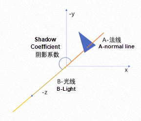
It is very simple to translate into code:
double angleCos = Math.abs(norm.z);For the sake of simple processing, we don't care whether the triangle faces the camera here, but it is necessary to determine whether the triangle is facing the camera based on ray tracing (we will refine it in the next article on ray tracing).
Now, we get the shadow coefficient, and it can be simply processed as:
public static Color getShade(Color color, double shade) {
    int red = (int) (color.getRed() * shade);
    int green = (int) (color.getGreen() * shade);
    int blue = (int) (color.getBlue() * shade);
    return new Color(red, green, blue);
}
Effect:
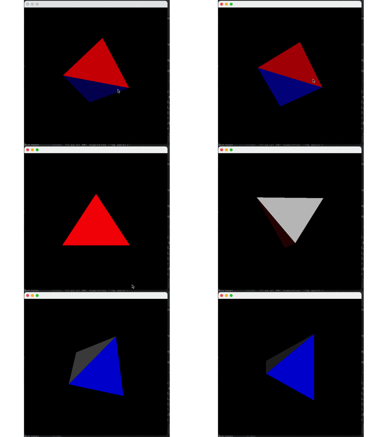
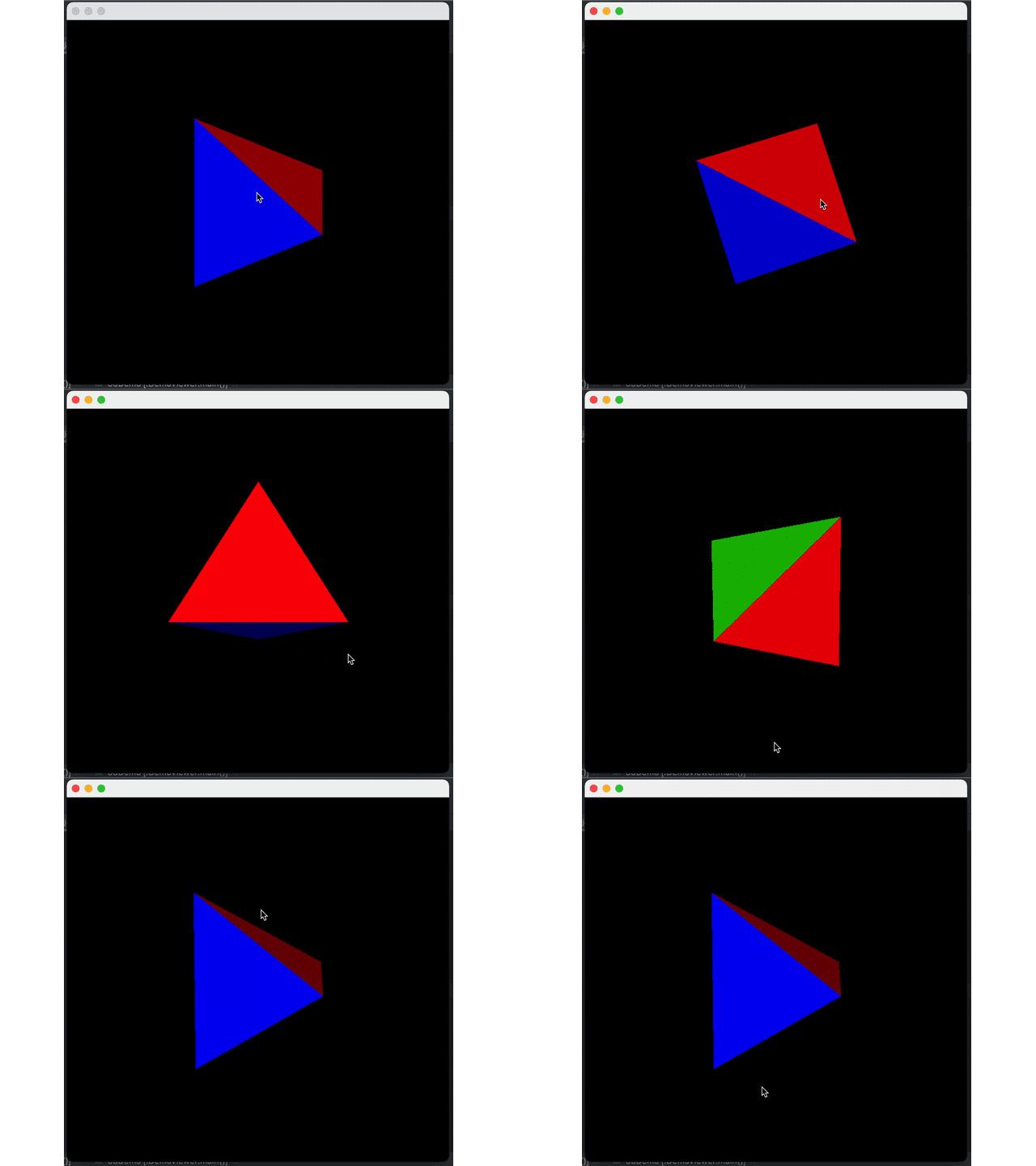
It can be seen that shadows do exist but decay too fast. This is because Java uses sRGB color space. Thus, we need to convert each color from scaled format to linear format, apply shadows, and then convert sRGB. However, the actual conversion is very complicated. We only make the simple and approximate conversion:
First, perform 2.2 power to linear space to calculate shadows and then perform 1/2.2 power back to sRGB space.
The parameters are based on the article entitled Gamma, Linear, sRGB and Unity Color Space, Do You Really Understand Them? (Article in Chinese)
Now, let's improve the following code:
    public static Color getShade(Color color, double shade) {

        double redLinear = Math.pow(color.getRed(), 2.2) * shade;
        double greenLinear = Math.pow(color.getGreen(), 2.2) * shade;
        double blueLinear = Math.pow(color.getBlue(), 2.2) * shade;

        int red = (int) Math.pow(redLinear, 1 / 2.2);
        int green = (int) Math.pow(greenLinear, 1 / 2.2);
        int blue = (int) Math.pow(blueLinear, 1 / 2.2);

        return new Color(red, green, blue);
}
Comparison of Effect:
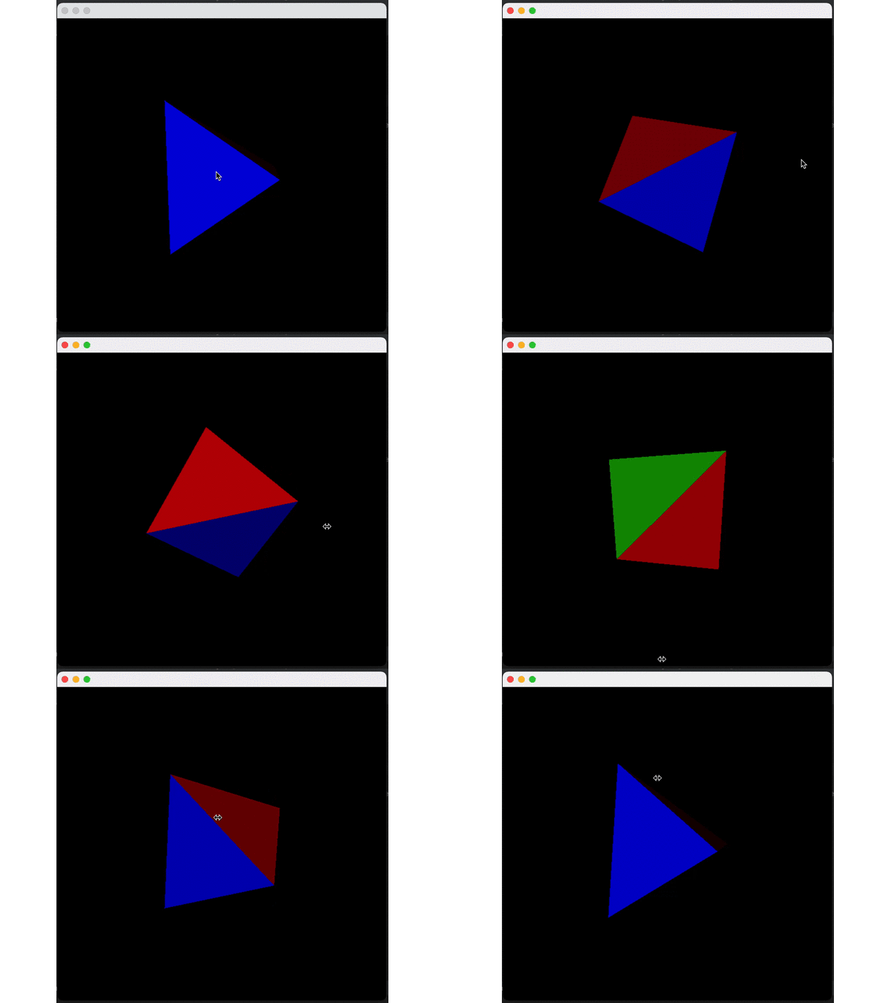
The surface of the object can be represented by simple splicing of triangles, so how should a curved surface be represented by triangles?*
One way is through the split-expansion of the plane.
A triangle can be split into four small triangles through the midpoints of its three sides, as shown in the following figure:
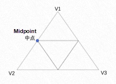
The code can be expressed as:
List< Triangle> result = new ArrayList<>();
        for (Triangle t : tris) {
                Vertex m1 =
                        new Vertex((t.v1.x + t.v2.x) / 2, (t.v1.y + t.v2.y) / 2, (t.v1.z + t.v2.z) / 2);
                Vertex m2 =
                        new Vertex((t.v2.x + t.v3.x) / 2, (t.v2.y + t.v3.y) / 2, (t.v2.z + t.v3.z) / 2);
                Vertex m3 =
                        new Vertex((t.v1.x + t.v3.x) / 2, (t.v1.y + t.v3.y) / 2, (t.v1.z + t.v3.z) / 2);
                result.add(new Triangle(t.v1, m1, m3, t.color,true));
                result.add(new Triangle(t.v2, m1, m2, t.color,true));
                result.add(new Triangle(t.v3, m2, m3, t.color,true));
                result.add(new Triangle(m1, m2, m3, t.color,true));
            }
}Now, we have some smaller triangles, and all we have to do is let their vertices expand to where the arc is.
Let's describe this process with a simple scenario in two-dimensional space:
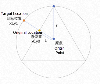
As shown in the figure above, we can get a proportionality coefficient by dividing (the distance between the original position and the origin: L) by (the distance from the vertex of the triangle to the origin: r). Then, divide its current coordinates x0 and y0 by the coefficient, respectively.
Distance formula:

The actual code is listed below:
        for (Triangle t : result) {
                for (Vertex v : new Vertex[]{t.v1, t.v2, t.v3}) {
                    double l = Math.sqrt(v.x * v.x + v.y * v.y + v.z * v.z) / Math.sqrt(30000);
                    v.x /= l;
                    v.y /= l;
                    v.z /= l;
                }
        }
Here, 3000 is the distance from the vertex of a triangle to the origin. Point (100, 100, 100) is used as an example: (100100+100100+100*100) = 30000
Let's first split a surface five times and do expansion to see the effect:
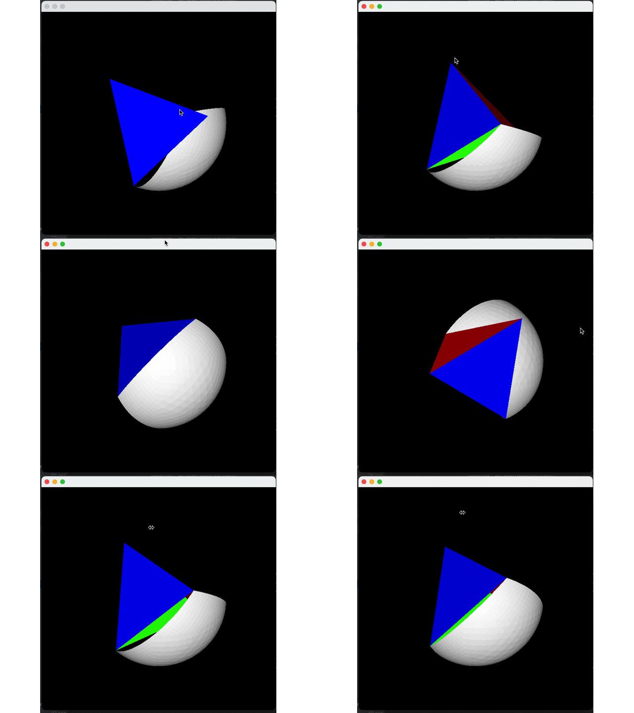
Expand all four interfaces to get a circle:
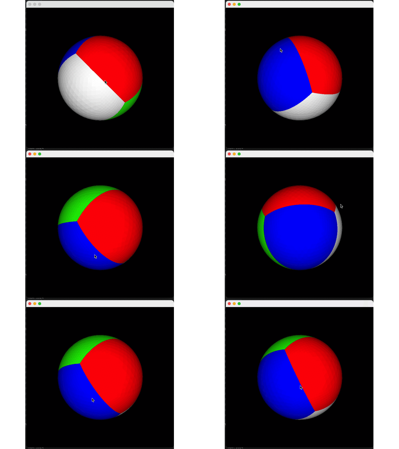
Then, we reduce the number of splits (twice) to see the effect:
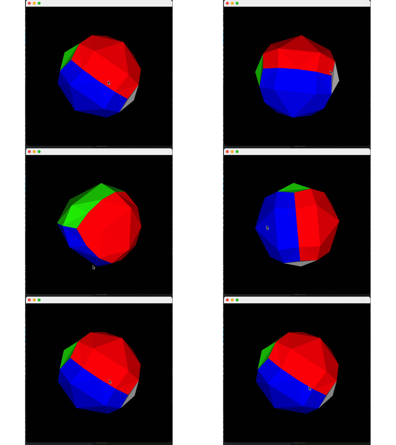
Finished!
https://gist.github.com/Rogach/f3dfd457d7ddb5fcfd99/4f2aaf20a468867dc195cdc08a02e5705c2cc95c
Pandas + SLS SQL: Data Pivot with Flexibility and High Performance

1,338 posts | 469 followers
FollowAlibaba Cloud Community - December 30, 2022
淘系技术 - October 28, 2020
wenlou - November 7, 2019
Alibaba Clouder - February 2, 2021
Alibaba Cloud Community - December 8, 2021
Alibaba Clouder - December 22, 2020

1,338 posts | 469 followers
Follow Remote Rendering Solution
Connect your on-premises render farm to the cloud with Alibaba Cloud Elastic High Performance Computing (E-HPC) power and continue business success in a post-pandemic world
Learn More Web Hosting Solution
Explore Web Hosting solutions that can power your personal website or empower your online business.
Learn More Web Hosting
Explore how our Web Hosting solutions help small and medium sized companies power their websites and online businesses.
Learn More EMAS Superapp
Build superapps and corresponding ecosystems on a full-stack platform
Learn MoreMore Posts by Alibaba Cloud Community