This topic describes how to use Vitis 2020.1 to create an image and load the image to a field programmable gate array (FPGA) on an f3 instance.
Prerequisites
An f3 instance that meets the following requirements is created.
The instance is created by using the FaaS_F30010_VITIS_2020_1 image. You can submit a ticket to obtain the image.
The size of the system disk is equal to or greater than 120 GiB.
A public IP address is assigned to the f3 instance.
A rule is added to the security group to which the f3 instance belongs to allow access over SSH port 22. For more information, see Add a security group rule.
The ID of the f3 instance is obtained from the Instances page of the Elastic Compute Service (ECS) console.
An Object Storage Service (OSS) bucket dedicated to FPGA as a Service (FaaS) is created.
The bucket and the f3 instance belong to the same account and are deployed in the same region. For information about how to create a bucket, see Create buckets.
Before you can manage FPGA-accelerated instances as a RAM user, you must perform the following operations:
Create a RAM user and grant permissions to the RAM user. For more information, see Create a RAM user and Grant permissions to a RAM user.
The permissions that you must grant to the RAM user include AliyunECSReadOnlyAccess, AliyunOSSFullAccess, and AliyunRAMFullAccess.
Go to the Cloud Resource Access Authorization page to authorize FaaS to access your resources.
Obtain the AccessKey ID and AccessKey secret of the RAM user.
Step 1: Connect to the f3 instance
A desktop environment and a Virtual Network Console (VNC) server are configured in the FaaS_F30010_VITIS_2020_1 image. We recommend that you connect to the f3 instance by using the VNC server. For more information, see Connect to an instance by using VNC.
Step 2: Initialize the software environment
Each time you create an f3 instance, you must perform the following operations to initialize the software environment.
Run the following command to start the VNC server with the specified resolution:
vncserver -geometry 2560x1440The following information is returned.

Run the following command to initialize the software environment that is pre-installed in the FaaS_F30010_VITIS_2020_1 image. This software environment is required to use Vitis in FaaS.
source /root/faasTools/vitis_setup.shIf the following information is returned, the software environment is initialized.

Step 3: Create a project
After the environment is ready, you can start Vitis by running the vitis command, and create a project on the GUI of Vitis.
Run the
vitiscommand to start Vitis.If the following information is returned, Vitis is started.

Create a project on the GUI of Vitis.
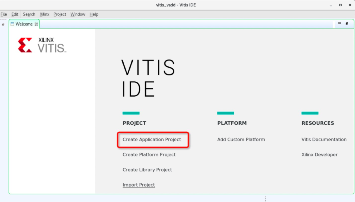
In the VITIS window, click Create Application Project below PROJECT.

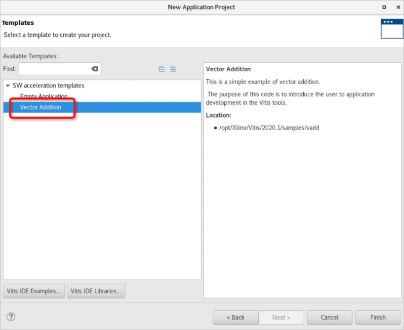
In the New Application Project dialog box, choose in the left-side section and click Finish.

Step 4: Use Vitis for emulation
Vitis supports two emulation modes: Emulation-SW and Emulation-HW.
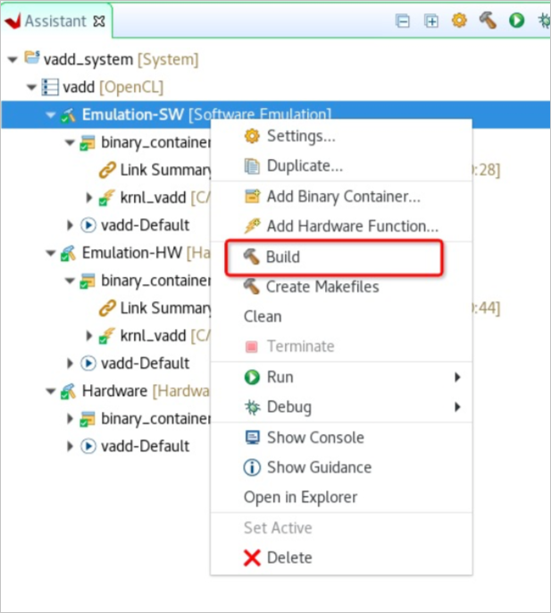
On the Assistant tab in the GUI of Vitis, choose .
Right-click Emulation-SW [Software Emulation] and select Build from the shortcut menu.

Right-click Emulation-SW [Software Emulation], and choose to emulate the model of the project that you created.
The following result is returned.

Step 5: Create an image
By default, the image files that are generated by Vitis include .bit files. However, you can upload only .dcp files in FaaS. Therefore, you must configure the relevant settings before you create an FPGA image.
In the upper-right corner of the Assistant tab, click the
 icon.
icon. In the Project Settings dialog box, choose .
In the vadd section on the right side, specify the following content for the V++ linker options configuration item. Click Apply. Then, click Apply and Close.
--advanced.param compiler.acceleratorBinaryContent=dcpReturn to the Assistant tab and choose .
Right-click Hardware [Hardware] and select Build from the shortcut menu to create the image.
It may take several hours to create the image. After the image is created, you can go to the
Hardwaredirectory in the project directory and run thelscommand to view the generated vadd binary file that can be executed by the host and the binary_container_1.xclbin image file. The following sample code shows the command output:[root@iz2zec7rvsxxxxxxx Hardware]# ls a.xclbin guidance.html binary_container_1.build guidance.pb binary_container_1-krnl_vadd-compile.cfg makefile binary_container_1-link.cfg package.build binary_container_1.ltx package.cfg binary_container_1.mdb src binary_container_1.xclbin vadd binary_container_1.xclbin.info vadd_Hardware.build.ui.log binary_container_1.xclbin.link_summary v++_package.log binary_container_1.xclbin.sh v++.package_summary common-config.cfg xcd.logRun the following command to generate a compressed file that can be uploaded to create an image:
[root@iz2zec7rvsxxxxxxx Hardware]# vitis_xclbin_split.sh binary_container_1.xclbinThe following command output is displayed:
XRT Build Version: 2.6.0 (2020.1)
       Build Date: 2021-03-08 10:50:41
          Hash ID: 80107ebc7376dafc8e1c9f5043c81c6f1dcc9dbb
------------------------------------------------------------------------------
Warning: The option '--output' has not been specified. All operations will
         be done in memory with the exception of the '--dump-section' command.
------------------------------------------------------------------------------
Reading xclbin file into memory.  File: binary_container_1.xclbin

Section: 'BITSTREAM'(0) was successfully written.
Format: RAW
File  : 'faas20210311-092706.dcp'
Leaving xclbinutil.
XRT Build Version: 2.6.0 (2020.1)
       Build Date: 2021-03-08 10:50:41
          Hash ID: 80107ebc7376dafc8e1c9f5043c81c6f1dcc9dbb
------------------------------------------------------------------------------
Warning: The option '--output' has not been specified. All operations will
         be done in memory with the exception of the '--dump-section' command.
------------------------------------------------------------------------------
Reading xclbin file into memory.  File: binary_container_1.xclbin

Section: 'EMBEDDED_METADATA'(2) was successfully written.
Format: RAW
File  : 'faas20210311-092706.xml'
Leaving xclbinutil.
to_aliyun/
to_aliyun/faas20210311-092706.xml
to_aliyun/faas20210311-092706.dcp
Generate Image :Image20210311-092706.tar.gz
The preceding command output shows that the Image20210311-092706.tar.gz file is generated. You can upload the file to create an image. For more information about how to create an image by using the faasutil tool, see Use faasutil.
NoteThe faasutil tool is pre-installed in the FaaS_F30010_VITIS_2020_1 image. You can use the faasutil tool after you run the
source /root/faasTools/vitis_setup.shcommand.
Step 6: Verify the result on an FPGA
After you use the faasutil tool that is pre-installed in the FaaS_F30010_VITIS_2020_1 image to create an image and load the image to an FPGA, you can check whether the image is loaded to the FPGA by using the CLI or the GUI of Vitis.
Use the GUI of Vitis for verification:
On the Assistant tab in the GUI of Vitis, choose .
Right-click Hardware [Hardware] and choose .
The following result is returned. The result shows that the image is loaded to the FPGA.

Use the CLI for verification:
In the
Hardwaredirectory of the project directory, run the following command to check whether the image is loaded to the FPGA:[root@iz2zec7rvsxxxxxxx Hardware]# ./vadd binary_container_1.xclbinThe following result is returned. The result shows that the image is loaded to the FPGA.
Loading: 'binary_container_1.xclbin'
TEST PASSED