Overview
If you have any questions about the request forwarding and TCP connection in SLB, see the layer -4 and layer -7 Listener Request interaction content described in this topic.
Description
Introduction to the environment for packet capture
47.*. *.241: public IP address of the client.
121.*. *.252: public IP address of the SLB instance.
172.*. *.252: the internal IP address of the backend ECS instance.
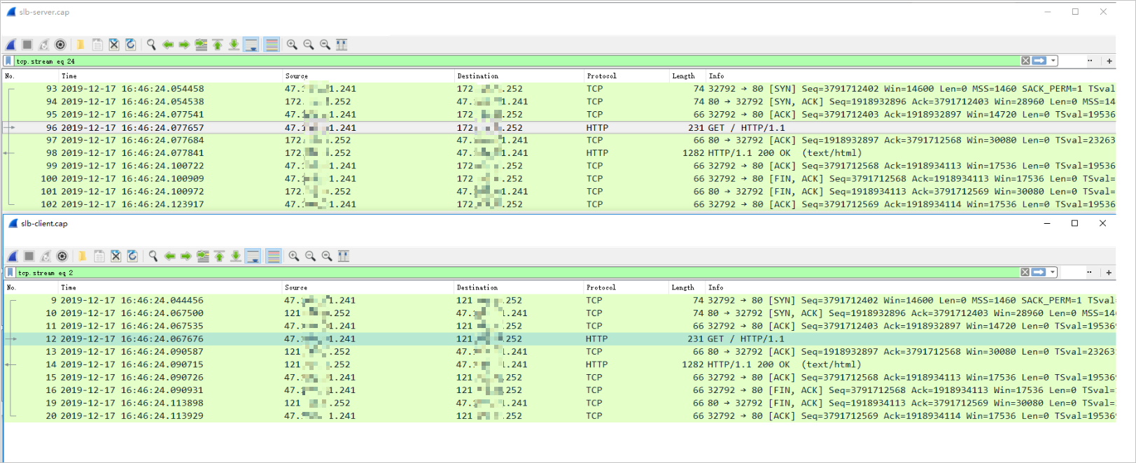
Layer -4 TCP packets
A connection-oriented protocol. A reliable connection must be established with the peer side before data can be sent and received. The source IP addresses can be viewed at the network layer. When the SLB forwards the traffic, the request packet only passes through the LVS, and then is transparently transmitted to the backend server. In terms of inbound requests, the SLB role is similar to that of the EIP directly bound to the ECS instance.
Back-end server packets: the packets sent from the client's public IP address are used to establish a TCP connection after a three-way handshake.
Client-side packets: establish a TCP connection after a three-way handshake with the public IP address of the SLB instance.

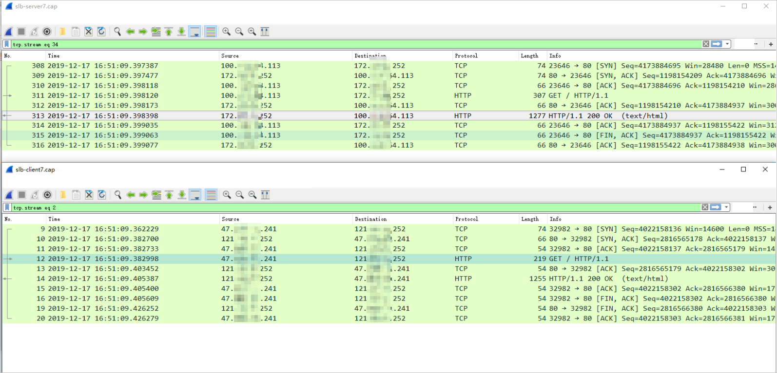
HTTP layer -7 listener message
The backend Server does not directly connect to the client. SLB only acts as a reverse proxy. During the request processing, it passes through the LVS cluster and Tengine cluster. (for the first request made by HTTPS, the client also needs to pass through the Key Server.)
Backend server packet: After a three-way handshake between the TCP connection and the SLB back-to-source IP addresses (generally 100 packets), a TCP connection is established.
Client-side packets: the TCP connection is established after a three-way handshake with the public IP address of the SLB instance.

Application scope
SLB