This topic describes how to create virtual private cloud (VPC) peering connections to enable multiple VPCs to use the same Internet NAT gateway. This way, the VPCs can access the Internet.
Background information
A VPC peering connection is a private network connection between two VPCs. You can enable two VPCs to communicate with each other by establishing a VPC peering connection. You can connect multiple VPCs by creating multiple VPC peering connections. For example, you created three VPCs named VPC1, VPC2, and VPC3. To connect the VPCs, you can create a VPC peering connection between VPC1 and VPC2, a connection between VPC2 and VPC3, and a connection between VPC1 and VPC3. This topic describes how to create a VPC peering connection between two VPCs to enable the VPCs to share an Internet NAT gateway.
For more information about VPC peering connections, see Overview.
Example scenario
In the following example, a company created two VPCs named VPC1 and VPC2 in the China (Hangzhou) region. vSwitch1 is created in VPC1, and an Elastic Compute Service (ECS) instance named ECS1 is created in vSwitch1. vSwitch2 is created in VPC2, and an ECS instance named ECS2 is created in vSwitch2. Due to business requirements, VPC1 and VPC2 need to access the Internet.
You create a VPC peering connection between VPC1 and VPC2, configure routes, and then create an Internet NAT gateway in VPC1. Then, you can create an SNAT entry on the Internet NAT gateway to enable VPC1 and VPC2 to access the Internet.

Prerequisites
VPCs and vSwitches are created as described in the following table. For more information, see Create and manage a VPC.
VPC name
Region
CIDR Block
vSwitch name
Zone and CIDR block
VPC1
China (Hangzhou)
192.168.0.0/16
vSwitch1
Hangzhou Zone H, 192.168.0.0/24
China (Hangzhou)
192.168.0.0/16
vSwitch2
Hangzhou Zone H,192.168.5.0/24
VPC2
China (Hangzhou)
172.16.0.0/12
vSwitch2
Hangzhou Zone H, 172.16.0.0/16
ECS1 is created in vSwitch1, and ECS2 is created in vSwitch2. For more information, see Create an instance on the Custom Launch tab.
Procedure

Step 1: Create an Internet NAT gateway
Create an SNAT-enabled Internet NAT gateway in VPC1.
- Log on to the NAT Gateway console.
On the Internet NAT Gateway page, click Create Internet NAT Gateway.
When you create an Internet NAT gateway for the first time, click Create in the Notes on Creating Service-linked Roles section of the buy page to create a service-linked role. After the service-linked role is created, you can create Internet NAT gateways.
 For more information, see Service-linked roles.
 On the Internet NAT Gateway page, set the following parameters and click Buy Now.
Parameter
Description
Billing Method
By default, Pay-As-You-Go is selected. You can pay for resources after you use them. For more information, see Billing of Internet NAT gateways.
Resource Group
Select the resource group to which the VPC belongs. For more information, see Resource group overview.
Tags
Tag Key: Select or enter a tag key.
You can specify at most 20 tag keys. A tag key can be up to 128 characters in length. It cannot start with aliyun or acs:, and cannot contain http:// or https://.
Tag Value: Select or enter a tag value.
You can specify up to 20 tag values. A tag value can be up to 128 characters in length. It cannot start with aliyun or acs:, and cannot contain http:// or https://.
Region
Select the region where you want to create the Internet NAT gateway.
In this example, China (Hangzhou) is selected.
VPC
Select the VPC for which you want to create the Internet NAT gateway. After the Internet NAT gateway is created, you cannot change the VPC to which the Internet NAT gateway belongs.
In this example, VPC1 is selected.
Associate vSwitch
Select the vSwitch to which the Internet NAT gateway belongs.
In this example, vSwitch 2 is selected.
Metering Method
By default, Pay-By-CU is selected. You are charged based on the resources that you use. For more information, see Billing of Internet NAT gateways.
Billing Cycle
By default, By Hour is selected. Fees are calculated on an hourly basis. If you use an Internet NAT gateway for less than 1 hour, the usage duration is rounded up to 1 hour.
Instance Name
Enter a name for the Internet NAT gateway.
In this example, Internet-NAT-Gateway is used.
Access Mode
Select whether to enable SNAT for the resources in the specified VPC. Supported options:
SNAT for All VPC Resources: If you select this value, the Internet NAT gateway is created in unified access mode. After the Internet NAT gateway is created, all resources in the VPC can access the Internet by using the SNAT feature of the NAT gateway.
If you select SNAT for All VPC Resources, you must also specify an elastic IP address (EIP).
Configure Later: If you select this value, you can configure the Internet NAT gateway in the console after you complete the payment.
If you select Configure Later, only the Internet NAT gateway is created. No SNAT entry is created.
In this example, SNAT for All VPC Resources is selected.
EIP
Select an EIP to associate with the Internet NAT gateway. You can specify the EIP in one of the following ways:
Select EIP: Select an existing EIP from the EIP drop-down list.
Purchase EIP: Purchase a pay-as-you-go EIP in the region where the Internet NAT gateway is deployed.
In this example, Purchase EIP is selected. By default, the Line Type parameter of the EIP is set to BGP(Multi-ISP). The Security Protection parameter is set to Default. You can set the Maximum Bandwidth parameter and set Metering Method to Pay-By-Data-Transfer.
On the Confirm page, confirm the configurations in the order, read and select Terms of Service, and then click Confirm.
Click Return to Console. On the Internet NAT Gateway page, find the Internet NAT gateway that you created and click its ID.
On the Basic Information tab, view the route information in the VPC Routes that Point to the NAT Gateway section. The route table to which the route belongs is the system route table of VPC1. The destination CIDR block of the route is 0.0.0.0/0, and the next hop is the Internet NAT gateway.
Click the SNAT Management tab. In the Used in SNAT Entry section, you can view the SNAT entry that is created. VPC1 can access the Internet through this SNAT entry.
Step 2: Create a VPC peering connection
Log on to the VPC console.
In the left-side navigation pane, click VPC Peering Connection.
In the top navigation bar, select the region where you want to create a VPC peering connection.
In this example, China (Hangzhou) is selected.
If this is the first time you create a VPC peering connection, click Activate CDT on the VPC Peering Connection page, and click Activate in the message that appears.
If the VPCs belong to different Alibaba Cloud accounts, make sure that both the requester and accepter accounts have the Cloud Data Transfer (CDT) service activated.
On the VPC Peering Connection page, click Create VPC Peering Connection.
On the Create VPC Peering Connection page, set the following parameters and click OK.
Parameter
Description
Peering Connection Name
Enter a name for the VPC peering connection.
Resource Group
Select a resource group for the VPC peering connection.
Requester VPC
Select a requester VPC from the drop-down list.
In this example, VPC1 is selected.
Accepter Account Type
Select whether the requester VPC and the accepter VPC belong to the same Alibaba Cloud account. Valid values:
In this example, Same-Account is selected.
Accepter Region Type
Select whether the requester VPC and the accepter VPC belong to the same region. Valid values:
In this example, Intra-Region is selected.
Accepter VPC
Select the accepter VPC.
In this example, VPC2 is selected.
On the VPC Peering Connection page, check the status of the peering connection.
An activated VPC peering connection is in the Activated state and is ready for use.
You can view the following information about the requester VPC and accepter VPC: the VPC ID, region, CIDR block, and owner Alibaba Cloud account.
Step 3: Configure routes
Add routes to VPC1 and VPC2 to manage traffic.
Log on to the VPC console.
In the left-side navigation pane, click VPC Peering Connection.
On the VPC Peering Connection page, find the peering connection that you want to manage and perform the following steps to add routes:
Add a route to the requester VPC (VPC1)
Click Configure Route in the Requester VPC column.
In the Configure Route dialog box, set the following parameters and click OK.
Parameter
Description
VPC
The requester VPC is automatically displayed.
Route Table
Select a route table associated with the VPC from the drop-down list.
Name
Enter a name for the route.
Destination CIDR Block
Enter a destination CIDR block for the route.
In this example, IPv4 CIDR Block is selected, and 172.16.0.0/12 is used. This is the CIDR block of VPC2.
Next Hop
The next hop is automatically displayed.
Add a route to the accepter VPC (VPC2)
Click Configure Route in the Accepter VPC column.
In the Configure Route dialog box, set the following parameters and click OK.
Parameter
Description
VPC
The requester VPC is automatically displayed.
Route Table
Select a route table associated with the VPC from the drop-down list.
Name
Enter a name for the route.
Destination CIDR Block
Enter a destination CIDR block for the route.
In this example, IPv4 CIDR block is selected and 0.0.0.0/0 is used. This ensures that VPC2 can use the Internet NAT gateway to access the Internet.
Next Hop
The next hop is automatically displayed.
After the route is configured, you can click the ID of the VPC peering connection on the VPC Peering Connection page. Then, you can view the route on the Route Entry List tab.
Step 4: Test the network connectivity
Test the connectivity of the VPC peering connection.
Log on to ECS1 in VPC1. For more information, see Methods for connecting to an ECS instance.
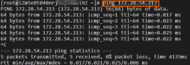
Run the
pingcommand topingthe private IP address of ECS 2 in VPC2.If you receive echo reply packets as shown in the following figure, data can be transferred from the requester to the accepter.
The test result shows that ECS1 can access ECS2.

Log on to ECS2 in VPC2.
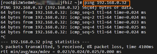
Run the
pingcommand topingthe private IP address of ECS1 in VPC1.If you receive echo reply packets as shown in the following figure, data can be transferred from the accepter to the requester.
The test result shows that ECS2 can access ECS1.

Check whether ECS1 and ECS2 can access the Internet.
Log on to ECS1 in VPC1.
Run the
ping www.aliyun.comcommand.If you receive echo reply packets as shown in the following figure, ECS1 can access the Internet.
The test result shows that ECS1 can access the Internet.

Log on to ECS2 in VPC2.
Run the
ping www.aliyun.comcommand.If you receive echo reply packets as shown in the following figure, ECS2 can access the Internet.
The test result shows that ECS2 can access the Internet.
