This topic describes how to use two Express Connect circuits and an Express Connect Router (ECR) to connect a data center (IDC) to the cloud over active/standby connections and enable communication with a virtual private cloud (VPC).
Example
An enterprise has a data center (IDC) in the China (Beijing) region and has created a transit router (TR) and a VPC in the same region. It needs to use an ECR to allow servers in the IDC to access cloud services over active/standby connections. Normally, traffic is forwarded only through the active connection. When Bidirectional Forwarding Detection (BFD) detects that the active connection is unreachable, traffic is switched to the standby one to ensure that services are not affected.
The procedure is as follows:
Deploy Express Connect circuits: Deploy two circuits to connect customer-premises equipment (CPE) devices in the IDC to VBRs, forming active/standby connections.
Create VBRs: Create two VBRs (VBR1 and VBR2) in the China (Beijing) region to serve as private network bridges between the IDC and the VPC.
Create an ECR: Create an ECR to serve as a forwarding service component between the IDC and the VPC.
Attach the VBRs and the TR to the ECR: Attach VBR1, VBR2, and the TR to the ECR to establish a logical association between the Express Connect circuits and cloud resources.
Configure BGP and enable BFD: Configure Border Gateway Protocol (BGP) dynamic routing between the IDC and the VBRs, and enable the BFD feature to implement rapid route convergence and automatic link failover.

Prerequisites
You have created a VPC in the China (Beijing) region and deployed services on ECS instances in the VPC.
You have created a TR in the China (Beijing) region and created a VPC connection for the TR.
Make sure that the rules of the security group attached to the ECS instance in the VPC allow traffic from the IDC. For more information, see Add a security group rule.
Procedure
Step 1: Apply for physical ports
In this topic, you can apply for ports in high-reliability mode, which provides powerful disaster recovery capabilities. After you submit the application, the system creates two physical port instances.
Step 2: Create VBRs
Log on to the Express Connect console and select the China (Beijing) region in the top navigation bar.
On the Physical Connection page, click the target physical port instance. On the details page, click Create VBR to create VBR1.
In the Create VBR panel, select Current Account as the account type, configure the following key parameters, and then click OK.

Repeat the preceding steps to create VBR2, and then click OK.

Step 3: Create an ECR and attach it to the TR and VBRs
Create an ECR
In the navigation pane on the left, click , and click Express Connect Router (ECR).
In the dialog box, enter
64512for ASN, keep the default values for other parameters, select the check box to agree to the billing rules, and then click OK.
Attach the ECR to the VBRs
Click the ID of the target ECR instance. On the VBR tab, click Associate VBR.
In the dialog box that appears, configure the following parameters and click OK.
Resource Ownership: Select
Same Account.Region:
China (Beijing).Network Instance: Select the VBR1 instance that you created.
Repeat the preceding steps to attach the ECR to VBR2.
Attach the ECR to the TR
Click the ID of the target ECR instance, and then click the TR tab.
Click Associate TR. In the dialog box, configure the following parameters, keep the default values for unlisted parameters, and then click OK.
CEN ID: Select the CEN instance that you created.
Region:
China (Beijing).TR: Select the transit router instance that you created.
Step 4: Configure BGP and enable BFD
You must configure a BGP peer between the on-premises gateway device and the VBR. When the BGP peer status is Established, the BGP session is successfully established and can start exchanging routing information.
After the peer relationship is established, the IDC can automatically learn cloud routes through BGP. Advertise the IDC CIDR block from the on-premises gateway device so that the VBR can automatically learn the routes to the IDC. After the preceding configurations are complete, servers in the IDC can access cloud resources.
Configure BGP routes on the VBRs
Log on to the Express Connect console to configure BGP routes for VBR1.
In the navigation pane on the left, click Virtual Border Routers (VBRs). Find the target VBR1 instance and click its ID. On the details page, configure BGP routes:
Click Create BGP Group, configure the following parameters, and then click OK.
Peer ASN: Enter the AS number of the IDC network, which is
6***3.Local ASN: Enter the AS number of the Alibaba Cloud side, which is
64512. The BGP ASN of the VBR inherits the ASN of the ECR.
Click Create BGP Peer, configure the following parameters, select Enable BFD, and then click OK.
BGP Groups: Select the BGP group that you created.
BGP Peer IP: Enter the IP address of the BGP peer. In this topic, enter the IP address of the interface on CPE1 that connects to the Express Connect circuit, which is 10.10.1.5.
Repeat the preceding steps to configure BGP routes for VBR2.
Configure BGP routes in the data center
BGP routes advertised from the data center to the VPC
On CPE1 and CPE2, adjust the AS-Path length of the route to the 192.168.0.0/16 CIDR block advertised from the IDC to control the route selection priority from the IDC to the VPC. A shorter AS-Path indicates a higher priority.
In this topic, an AS-Path is prepended for CPE2. By increasing the AS-Path length, the priority of the route to the IDC CIDR block advertised from the VBR2 instance to the VPC is reduced. This makes VBR1 the active link and VBR2 the standby link. As a result, the two Express Connect circuits form active/standby links for traffic from the cloud to the data center.
The configuration commands may vary based on the vendor and device. This topic lists only the key parameters. For specific commands, consult your device vendor.
Configuration | CPE1 | CPE2 |
VLAN Tag | 1308 | 1309 |
Network | 192.168.0.0/16 | 192.168.0.0/16 |
BGP ASN | 6***3 | 6***4 |
Interface IP | 10.10.1.5 | 10.10.2.5 |
AS-Path | A | B, A |
BGP routes advertised from the VPC to the data center
In the IDC, adjust the BGP route selection attributes for the route to the VPC CIDR block 10.0.0.0/8 learned from VBR1 and VBR2. This makes VBR1 the active link and VBR2 the standby link. As a result, the two Express Connect circuits form active/standby links for traffic from the data center to the cloud.
Step 5: Verification and testing
Test network connectivity.
Log on to an ECS instance in the VPC and run the
ping <IP address of the client in the IDC>command to access the client in the IDC.The following response indicates that a network connection is established between the IDC and the VPC.

Run the
traceroutecommand to check whether the two Express Connect circuits provide active/standby links. Iftracerouteis not installed, you can run thesudo yum install traceroutecommand to install it. This command is applicable to CentOS.VPC-to-IDC direction
Log on to the ECS instance in the VPC and run the
traceroute <IP address of the client in the IDC>command. The following response indicates that traffic from the VPC to the IDC is forwarded through the active link VBR1.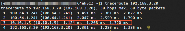
IDC-to-VPC direction
Log on to the client in the IDC and run the
traceroute <IP address of the ECS instance in the VPC>command. The following response indicates that traffic from the IDC to the VPC is forwarded through the active link VBR1.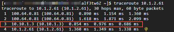
Simulate a VBR1 link failure. In this topic, the failure drill feature is used to simulate the disconnection of the active link VBR1 to test whether traffic is switched to the standby link.
Run the
traceroutecommand again to test whether traffic is switched to the VBR2 link.VPC-to-IDC direction
Log on to the ECS instance in the VPC and run the
traceroute <IP address of the client in the IDC>command. The following response indicates that traffic from the VPC to the IDC has been switched to VBR2.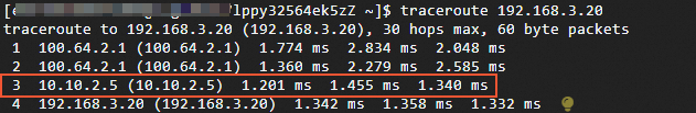
IDC-to-VPC direction
Log on to the client in the IDC and run the
traceroute <IP address of the ECS instance in the VPC>command. The following response indicates that traffic from the IDC to the VPC has been switched to VBR2.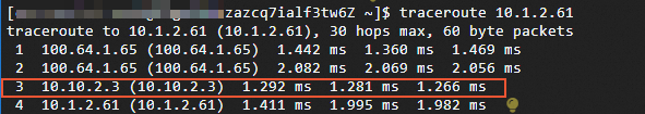
References
To implement load-balanced connections to the cloud, see Connect a data center to the cloud over load-balanced Express Connect circuits using an ECR.