By Chuheng

At first glance, the term "architecture drawing" seems somewhat obscure. However, when it comes to "engineering drawing", most programmers with an engineering background should already be familiar with it. I can even feel the ups and downs of those years in the dormitory with a compass on the left hand and a ruler on the right hand.
Software engineering is also engineering. Therefore, some basic theories of conventional engineering drawing are also applicable in the software industry. However, the differences between the software and traditional manufacturing industries are so essential that their demands and methods in cartography are quite different as well, which cannot be directly applied. As a practitioner in the software industry, you may not understand engineering drawing at all, but you must understand architecture drawing. This is a compulsory course for every programmer in their careers.
The second half of this article describes how to use graphs to describe and communicate your architectural design. It is worth emphasizing that this article will focus on the general methodology behind those excellent methods rather than on a single method or tool. It means that this article will focus on the essence, commonality and best practices of architecture drawing. I hope this article can serve as an introduction to stimulate everyone to follow, examine and think about the architecture and drawing part of your daily work. If this article can really help you improve the drawing efficiency and effect even just a little bit, that would be great.
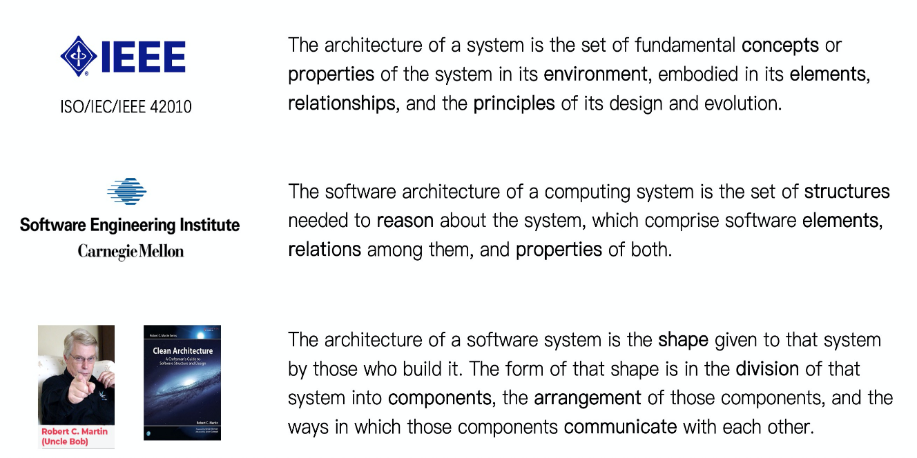
The definition shown by IEEE is that architecture is the set of fundamental concepts or properties of the system in its environment, embodied in its elements, relationships, and the principles of its design and evolution.
Software Engineering Institute of Carnegie Mellon University (CMU) defined the software architecture of a computing system is the set of structures needed to reason about the system, which comprise software elements, relations among them, and properties of both.
Uncle Bob defined architecture of software system in Clean Architecture is the shape given to that system by those who build it. The form of that shape is in the division of that system into components, the arrangement of those components, and the ways in which those components communicate with each other.
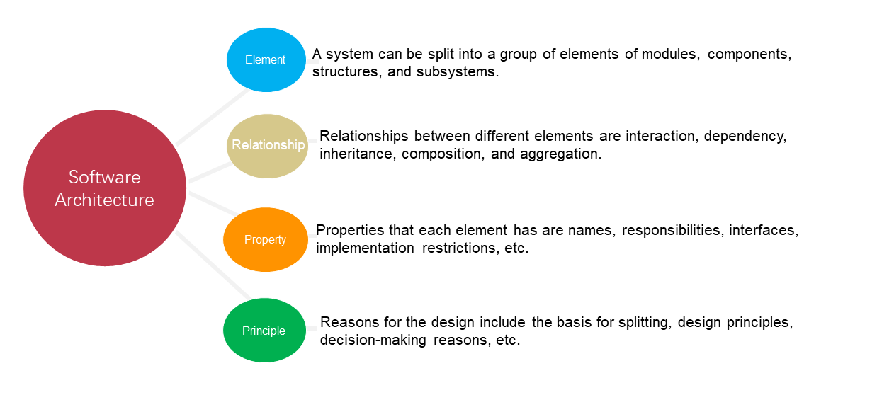
Based on authoritative definitions above, software system architecture usually contains following four types of core elements.
Recently, there is a very popular web series about a strange suspense story in a skyscraper called "A Murderous Affair in Horizon Tower". I want to ask a question here. Who built the skyscraper? Maybe you will think the question as meaningless that the skyscraper is just built by construction workers brick by brick. However, if you think about it again, you will find that there are a bunch of architects and civil engineers who are most concerned about the skyscraper. They don't work like construction workers, but without their hard work of those tedious and rigorous design drawings, skyscrapers cannot be erected as quickly and stably as self-built houses. In rural areas, self-built houses can be constructed just with workers' experience and imagination.
It is these blueprints that laid the basis for worker's division and cooperation of labor as well as acceptance criteria. Workers just need to follow blueprints and do their jobs. As long as blueprints are correct and there is no deviation in the construction process, the skyscraper will eventually be completed successfully.
Like the construction, automotive, or any other engineering industries, software also requires blueprints before it is coded. One of the most important blueprints is architecture design. With no architecture but only vague ideas, you might be able to create some nice and useful things such as Linux 0.01 like traditional craftsmen. However, it is unlikely that a complex software system on the scale of a skyscraper, for example, the modern Linux system, could be built in an engineering manner with a team. For one thing, the thinking ability of human is limited. So, we must rely on highly abstract and simplified blueprints of architecture to make the creation, understanding, analysis and management of complex systems feasible. For another, large systems that reach a certain level can only be completed through multiple division of labor. The architecture is just the important foundation for communication and collaboration among people.
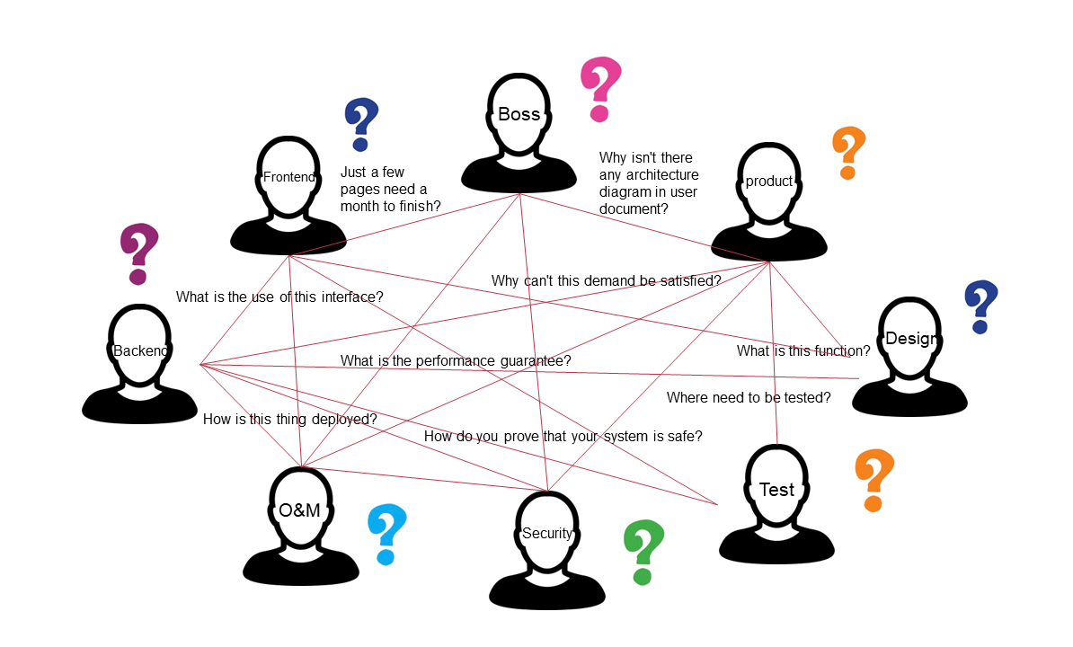
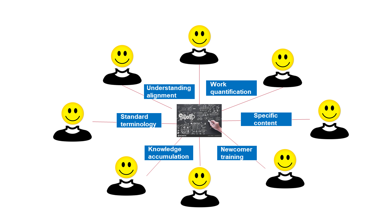
The final value output of a software project is the software system. As the soul and framework of the software system, the architecture can play following roles.
Knowledge accumulation and newcomer training: Architecture should be continually accumulated and maintained as document assets like important code. Moreover, architecture is an important basis for newcomers to understand and operate system quickly. Don't leave your system only with legacy code and without architecture documentation. Otherwise, you will be in struggling to maintain the project alive only with some leftover design memories from mouth to mouth.

How to measure the quality of a software product? The preceding figure shows the software product quality model defined by ISO/IEC 25010, which covers following eight aspects.
All points listed in the quality model above need to be considered in architecture design. Except function suitability, all other points belong to non-functional requirement, which is the standard for distinguishing good architectures from bad ones. In other words, good architecture design will not only satisfy the most basic functional requirement for the worst architecture design can do the same. More importantly, good architecture design also meets many other non-functional requirements.

You of course cannot have them all. Architecture is a game of tradeoff just like our life. The worst result is nothing will be done in the end. Good architects should seem like "know nothing", but actually "know everything". They should know all stakeholders in the system, try to mine all parties' concerns, balance their own decisions, and finally achieve the ultimate goal for all-win situation.
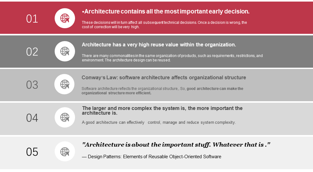
There are actually more reasons than those listed in this page.
After understanding concepts and the importance of architecture, you have just begun to become a real architect. The question of how to design a good architecture is obviously a broad and profound topic, but it is not the focus of this article. Therefore, only some basic principles and classic modes are presented in this article. Architecture design is closer to an empirical discipline. It is not enough to blurt out some mysterious and lofty theoretical concepts. You also need to put yourself into practice and try to deliberate architecture design through the combination with actual work and business scenarios. Or otherwise, you will always just discuss about theories.
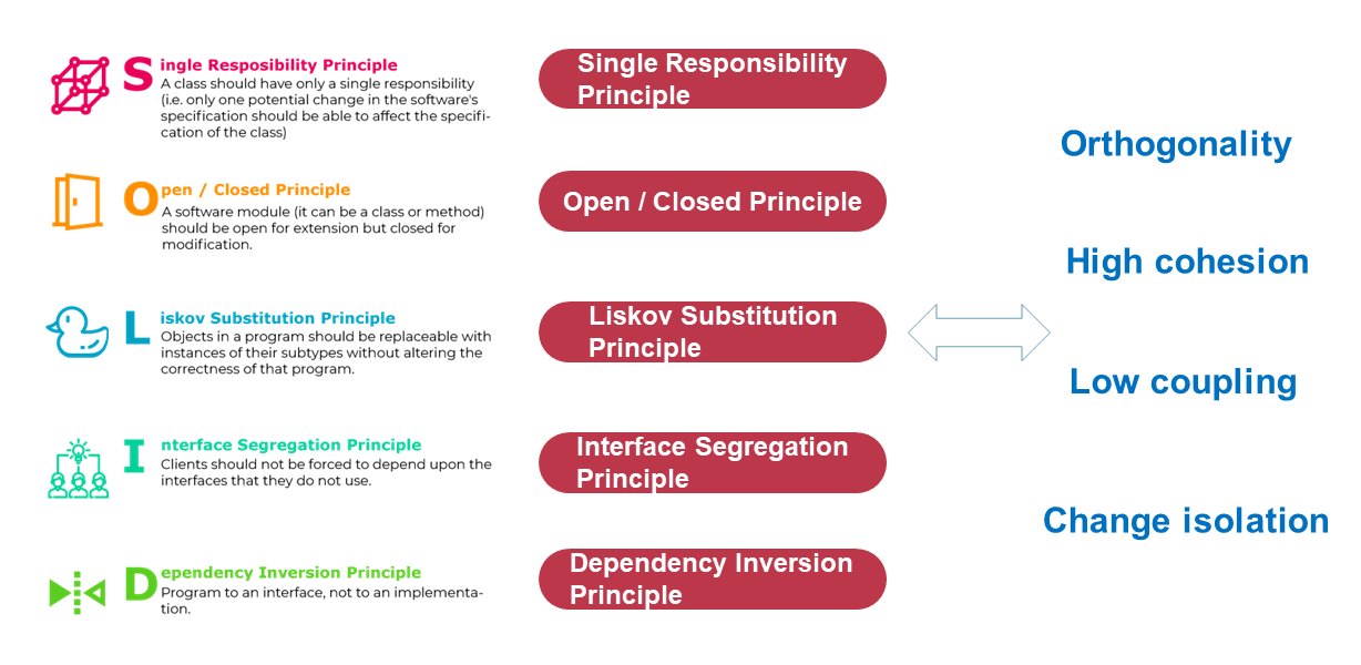
SOLID principles are a set of classic and popular architecture principles.
In addition, following principles will be obeyed as much as possible when designing the architecture. These principles are similar to the above SOLID principles in essence.
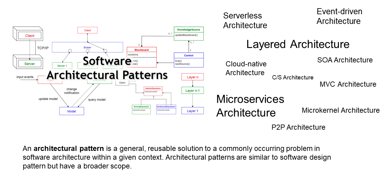
Architectural patterns are not same as design patterns we often discuss. However, if we interpret them only from the perspective of "patterns", the idea of both is the same, that is, a general and reusable solution to a commonly occurring problem within a given context. The main difference is that architecture patterns used at the architecture design level are more high-dimensionally abstract and more comprehensive.
Common architecture patterns include some traditional patterns such as layering, C/S, MVC and event driving, and also some new patterns such as cloud native, microservices, and Serverless. Different patterns have different applicable scenarios. A mature architect should be like a feelingless killer that always objectively evaluate and choose the most suitable solution for the moment, even if it will seem simple and boring. On the contrary, an immature architect always wants to do something, such as forced applying microservices architecture, rather than solving issues.
With a good architecture design, the road to the successful architecture has already reached more than half. It is just like a delighted young director who meets a good script for the first time. He seems to foresee the brilliant box office after the movie is on. Of course, the rest of the road is not as flat as imagined. The same design will have different qualities by different architects. A good architect should have the ability to describe a good architecture design. Even if he cannot add more points to the wonderful part, he should not lose points due to improper description of its form. Otherwise, he will feel so wronged and sad like losing points in writing in an exam.
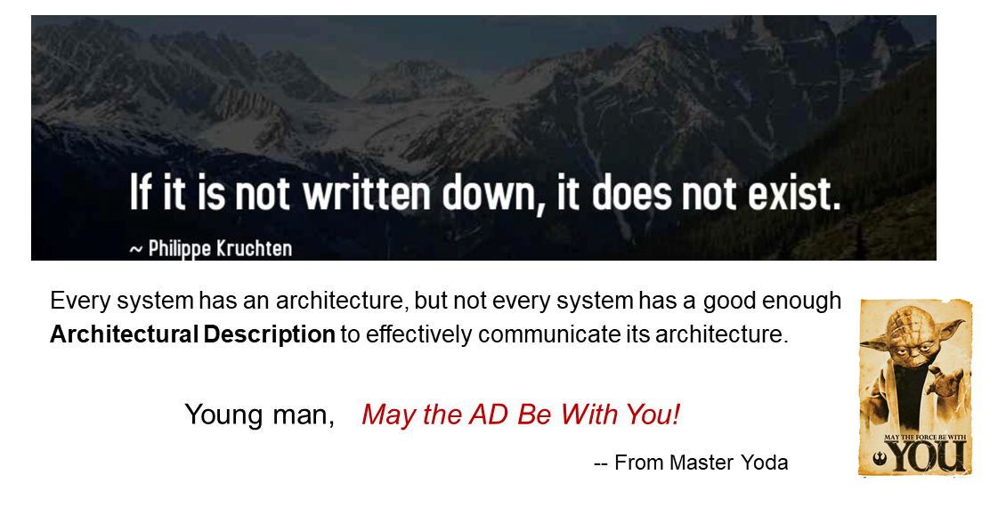
Why should I describe the architecture rather than just keeping it deeply in my mind? There is a proverb in the west that the faintest ink is better than the best memory.
Anything without persistence is volatile, just like memory. In addition, as mentioned earlier, architecture is the basis for communication and collaboration. Without architecture description for relative person in the object, the only carrier of communication and dissemination will be lost.
According to my personal observations, there is no objection to the "architecture demand description". So most projects produce some sample architecture description documents more or less. However, there is a huge difference between architecture description and good architecture description, which is even huger than the difference between "having architecture description" and "having no architecture description". If you have read countless architectural documents like me, you may feel the same.
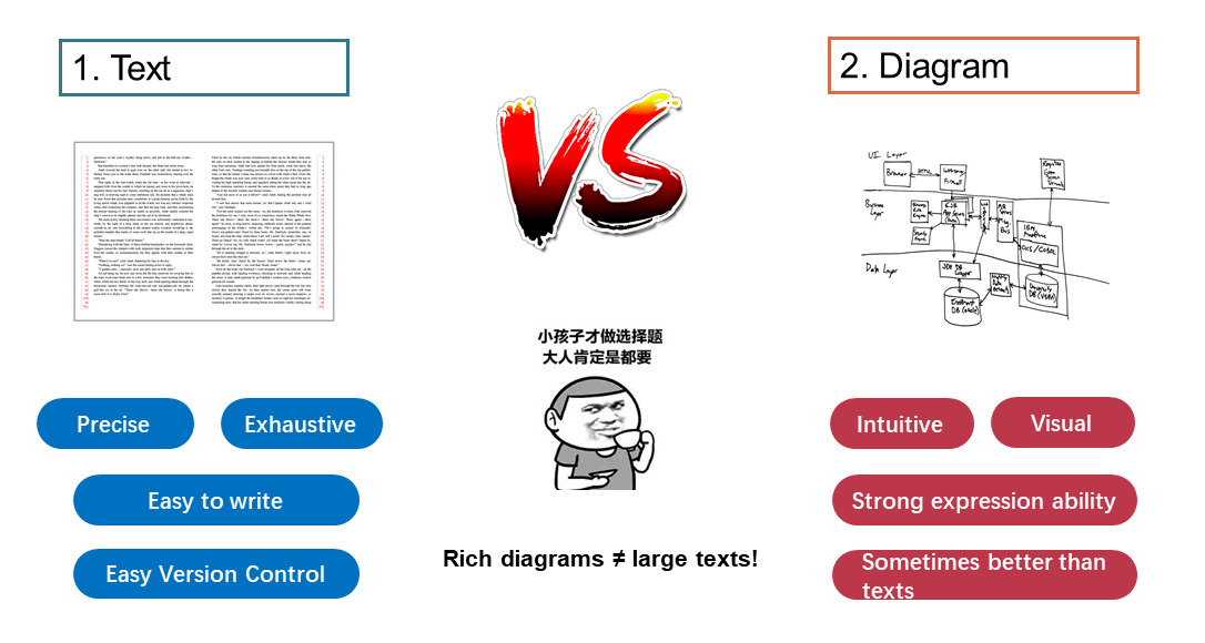
For a same thing, a writer uses words to describe it, while a painter uses paintbrushes to draw it. Both of them want to present the same information, but different ways of description will lead to huge difference in effect. Architecture description is also divided into text and diagram, each of which has its own advantages.
You may think that can't we have both text and diagram? Of course we can. The ideal architecture description must be illustrated with both text and diagram, but the real world is obviously crueler than an ideal one. In actual software programs, it is unlikely to give you enough time to produce a perfect architecture document first. Considering the return on investment (ROI), you will definitely give priority to diagram.
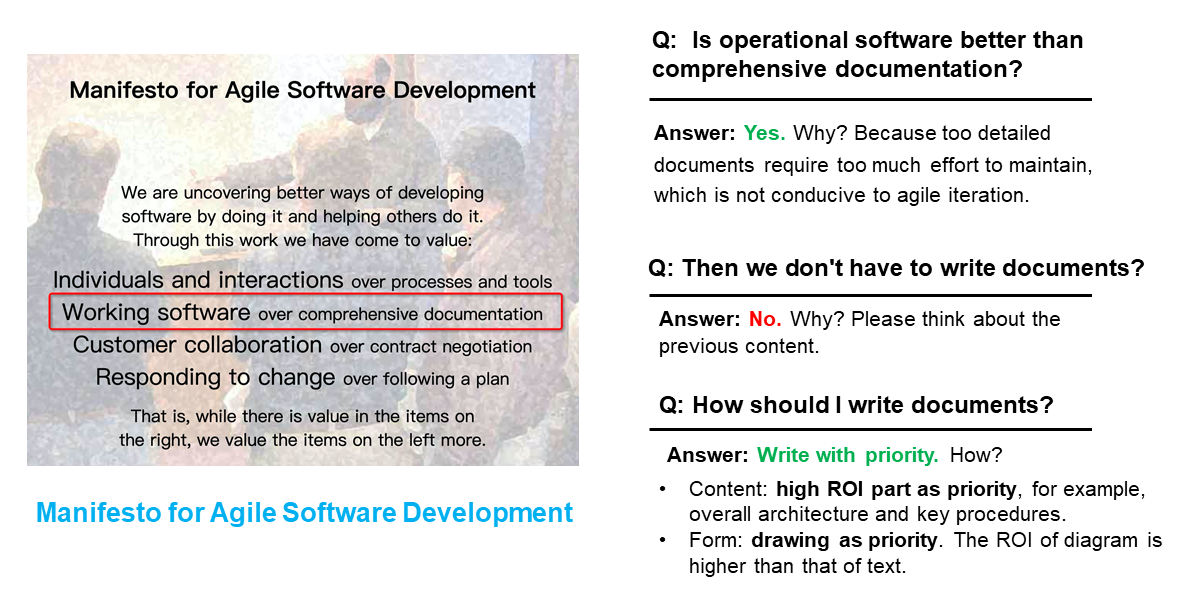
The Manifesto for Agile Software Development mentioned that working software is more important than comprehensive documentation. This, of course, does not mean that there is no need to write documents. It just advocates there is no need to write too comprehensive documents. The reason is that comprehensive documents expend a lot of writing and maintenance costs, which does not conform to agile development principles of small-step iteration and rapid response to changes.
So, in today's era of comprehensive agile development, how can we also follow the trend for more quickly writing architecture documentation? ROI is your friend, meaning that you should try to express the core content with simplest expressions. From content, the high ROI part is usually the top-level overall architecture or the core procedure. This is also reflected in the C4 model concept that will be introduced later. From form, diagram has an unparalleled expressive advantage compared with text, which is obviously a choice with higher ROI.
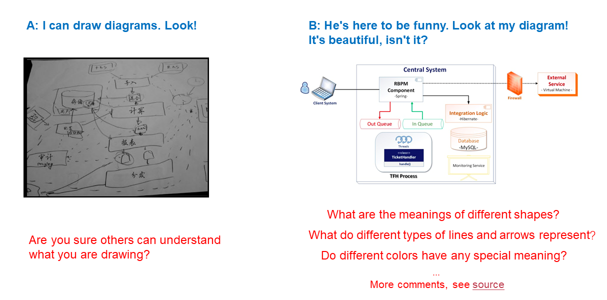
Is it necessary for us to learn how to draw? Architecture diagram is not art painting or just a bunch of stripes, and anyone with a little engineering knowledge can draw it. The painting is a bit ugly? It doesn't matter. You just need to align lines and frames and add colorful background gradient or something. Then it will look very professional.
Maybe you will pour scorn on that again and think that it is obviously not so simple. Indeed, everyone knows the truth. Architecture drawing, like engineering drawing, is a matter that needs to be taken seriously and rigorously. However, in reality, most people really don't have the time to do that. For example, the two common architecture diagrams posted above. Needless to say that the first diagram is good to satisfy yourself rather than show to others. The second diagram looks fine, but actually, when you measure it more carefully, you will find a lot of ambiguity and uncertainty in this diagram. For more information, please refer to the source article of this picture: The Art of Crafting Architectural Diagrams.
So, being able to draw diagrams doesn't mean being able to draw diagrams well. It is difficult to seize key points for drawing a nice and readable diagram only by intuition and comprehension. You still need to learn continuously and practice deliberately. In addition, wrong diagrams are often worse than no diagrams. Even if just thought that "It's OK to be just about right", you should at least understand some key elements of scientific drawing. These key elements will avoid blurring an already complicated project, or even confusing or misconducting users.

Before discussing specific drawing methods and tools, we need to erect clear drawing objectives. Tools are the ladder of human evolution. However, if tools are understood and used improperly, human will easily be restricted or even enslaved by tools in return, forgetting original objectives of inventing and using tools. There are already so many methods and tools for architecture drawing. The original objective I think is to turn drawing into a scientific engineering from a free craft, achieving its systemization, strictness, integrity and standardization. At the same time, the process of drawing can be repeatable, sustainable and efficient.
P.S: Please forgive me. I was too busy at that time, so pictures in PPT have to be very simple.
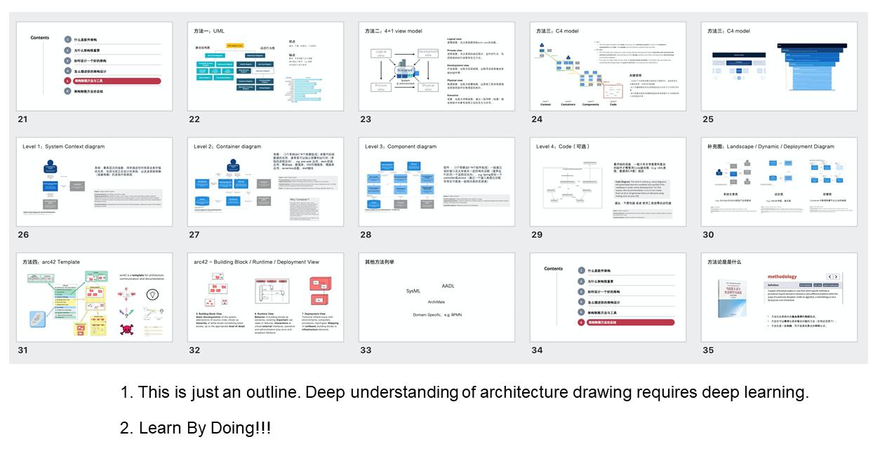
After brief introductions in previous chapters, I believe that everyone has enough understandings of background knowledge for architecture drawing. In this chapter, I will specifically list and describe some typical architecture drawing methods and tools. Some of which are common and some of which are rare. The focus is to hope that through the horizontal comparison of various methods, everyone can understand well on the nature of drawing methods.
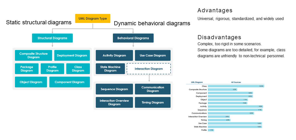
Unified modeling language (UML) is probably the most familiar drawing method for most people. The latest version of UML 2.x consists of following two types of diagrams.
The universal UML contains 14 different types of diagrams, which can comprehensively meet various drawing requirements in software design, including architecture drawing. At the same time, as UML regards itself as a language, it has rigorous definition on various notations and semantics without any uncertainty or ambiguity. In addition, after decades of development and promotion, UML has already become a standard norm widely used worldwide. The hidden value of UML is the low cost for communication within the team by supposing that most technicians can comprehend the meaning and usage of UML.
However, although UML was once regarded as the silver bullet in software design, it is still not omnipotent. The most criticized shortcoming of UML is that it is too complicated. It is not UML itself to blame because it is designed to be universal, rigorous and powerful enough after all. These goals run counter to simplicity, and let it evolve step by step into today's complicated and rigid language. Although we confidently supposed that most technicians can comprehend UML, I think an average of 20% would be good if you ask me how many of UML can they comprehend. Most of technicians just know several common class diagrams and sequence diagrams. It is estimated that it is even difficult for them to accurately express meanings of various arrows in class diagrams.
Whatever, UML should still be one of the most commonly used and necessary tools for every programmer. Of course, it should not be the only one, because there are some other good tools and methods that cannot be missed below.
What is "4 plus 1"? It doesn't matter if you haven't heard of it. Have you ever heard of the famous TV show named "6 plus 1"? "6 plus 1" has no relation with "4 plus 1" at all. They just sound similarly, like Sherry, Shirley, and Shirly.
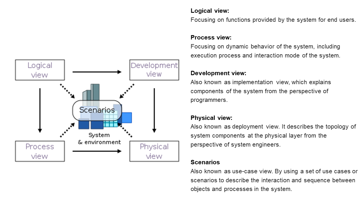
So, what exactly does "4 plus 1" mean? Wikipedia defines it as a kind of view model and architecture describing software-intensive systems through multiple coexisting views. These views are based on viewpoints of different project stakeholders, such as end users, developers, system engineers, and project managers. "4 plus 1" consists of four basic views and some selected use cases or scenarios, that is, additional "plus 1" view. Following are specific meanings of each view.
Although views of "4 plus 1" mentioned above are generally represented by UML diagrams, in fact, "4 plus 1" itself is a kind of universal view model. Marks and tools of drawing are not limited. For engineers, this partially theoretical method may not be directly used in their work, but one key architecture drawing idea of "4 plus 1" is very valuable. That is the architecture needs to go through various views for description, while these views are based on viewpoints of different project stakeholders. Only in this way can architecture descriptions be comprehensive, three-dimensional and objective.
C4 model is an abstraction-first architecture drawing method, which is also inspired by UML and "4 plus 1" view model, but is relatively simpler and more lightweight. C4 model is easy to be learned and used with only a small set of abstractions and diagrams.
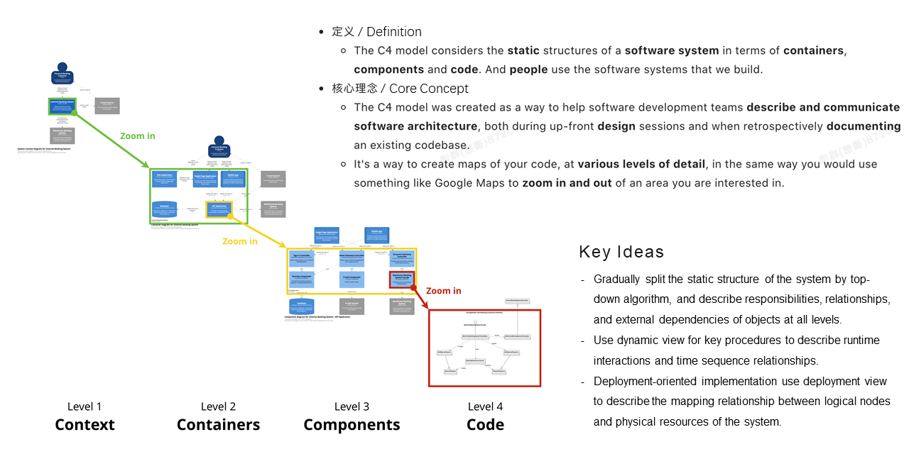
C4 model describes a static structure of the software system by abstraction such as containers, components, code, and people. Its core goal is to create maps of code, at various levels of details, in the same way as Google Maps to zoom in and out of an area. Its most crucial idea is to gradually split the static structure of the system by top-down algorithm, and describe responsibilities, relationships, and external dependencies of objects at all levels in sequence. In addition to the core hierarchical and static structure view, it also includes supplementary views such as dynamic view and deployment view.
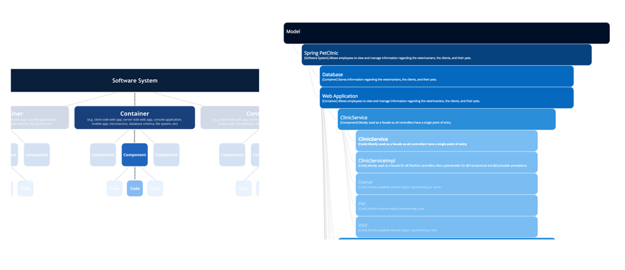
The figure on the left shows mapping relationships of abstractions in various levels of C4 model. One software system consists of one to N containers, while one container consists of one to N components and one component consists of one to N code structures. The figure on the right takes a simple Spring PetClinic as an example, demonstrating the hierarchy of a real software system in the C4 model. The top layer is the PetClinic software system, which can be split into several containers like databases and web applications. Web applications contain components like ClinicService, which includes components of ClinicService interface, ClinicService implementation, and domain objects such as Owner, Pet, and Visit.
Architecture drawing through C4 model is essentially the visualization of above-mentioned abstractions. The specific way is to create types of structural diagrams from rough ones to detailed ones in sequence, which are Context, Container, Component, and Code (optional). This is also the reason why it is called C4 model.
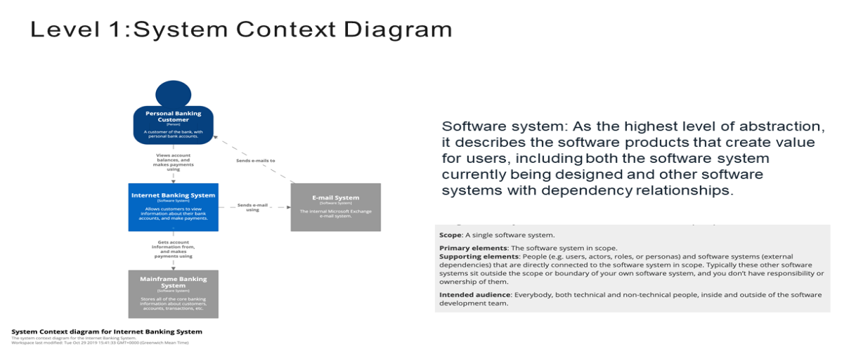
As the first level (L1), context diagrams of the system provide a big picture with the comprehensive view of the system. The big picture includes the central software system, peripheral users, and other systems with interactions. There are two key concepts in it.
When drawing context diagrams of the system, there is no need to care about any underlying details such as technology stacks and protocols. These diagrams have a large range of audiences, because anyone can understand and obtain enough information from them. It is true for technical and non-technical personnel, as well as members within and outside the team.
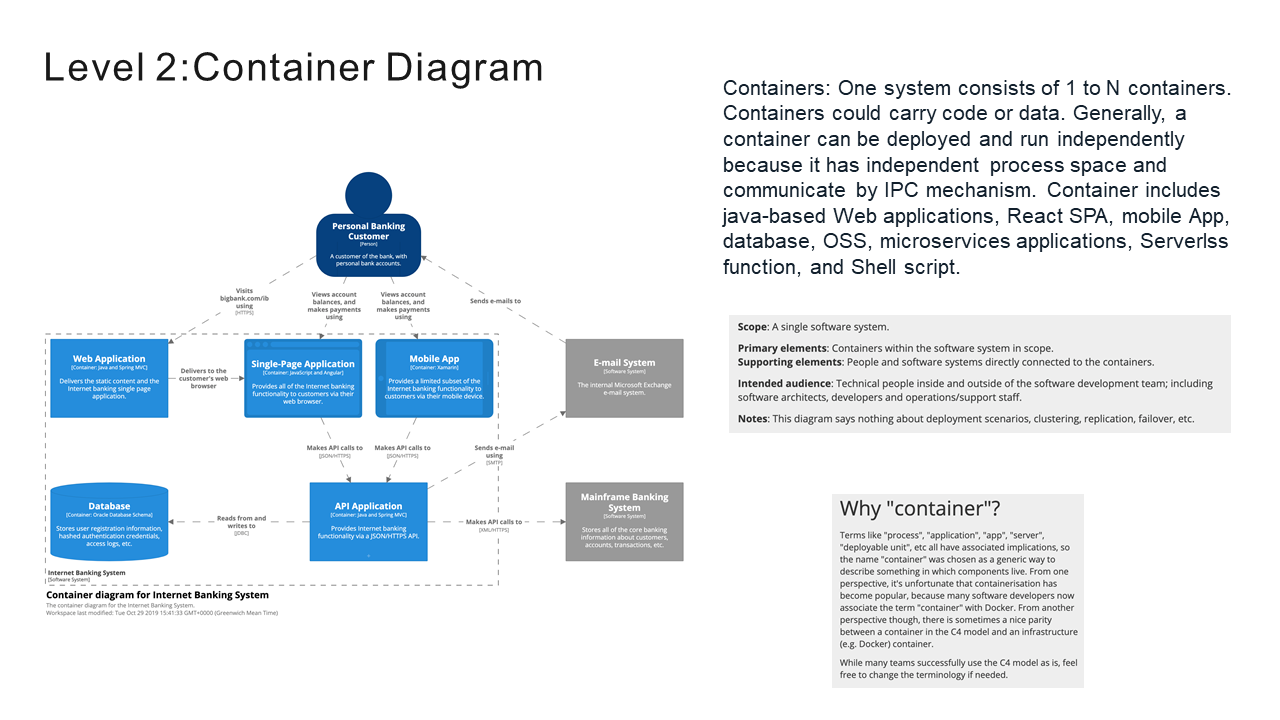
After understanding the positioning of the system in the entire IT environment through context diagrams, the next step is to enlarge the framework of the system and see in detail which containers are included. Here please pay enough attention to the differences between container and docker.
In the C4 model, a container is a single application or data storage. Generally, a container can be deployed and run independently because it has independent process space and communicate by IPC mechanism. The container includes Spring Boot microservices, React SPA, mobile App, database, Serverlss function, and Shell script.
The container diagram in the second level (L2) not only shows how to further divide responsibilities of the system. It also includes key architecture information such as main technology selection and communication between containers. This type of diagram is intended for all technical personnel, including architects, developers, O&M personnel, and support professionals.
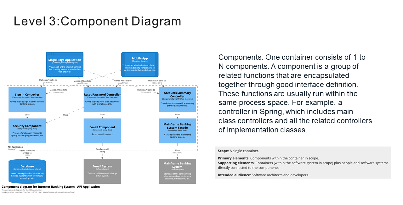
The next step is to partially zoom in containers in the system and further split each container into multiple components. In the C4 model, a component is a group of related functions that are encapsulated together through good interface definition. These functions are usually run within the same process space, for example, a controller in Spring. Controller includes not only main class controllers that define REST interfaces, but also all the related controllers of implementation classes, such as Service and Repository.
Similar to container diagrams, component diagrams of the third level (L3) include not only the division of container components, but also the responsibility definitions, technologies, and implementation details of each component. As layers deepen and details increase, the audiences range of component diagrams narrows. Target audiences generally only include software architects and developers. For other people, it is not necessary for them to understand, not mention that they are usually unable to understand.
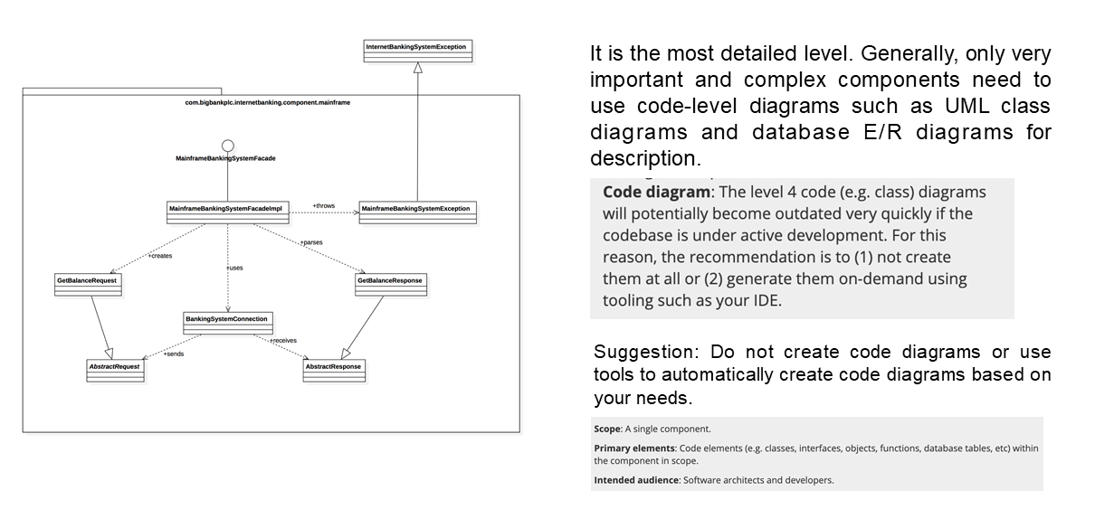
By scaling up the component, we will see the detailed information in bottom layer. This is the code of level 4 (L4). Of course, the so-called code here still takes the form of diagrams such as UML class diagrams and database E/R diagrams. These diagrams show the code structure in classes- or file-level granularity, but they are not the real code. Even so, code diagrams are too detailed in 99% of architecture description scenarios. On the one hand, they are numerous and have high cost of drawing. On the other hand, they are easy to be changed and have high maintenance costs. Therefore, only important and complex components need to use this layer for description. If you do need to draw code diagrams, you'd better give priority to the automatic ways. For example, many IDEs support automatic generation of UML class diagrams.
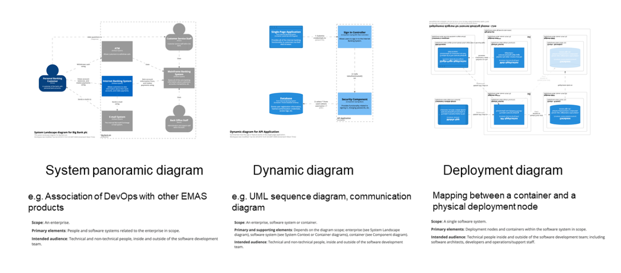
In addition to static structure diagrams of each level above, the C4 model also proposes a series of supplementary diagrams as follows.
With the combination of these supplementary diagrams, the C4 model could be a complete architecture drawing method for comprehensively describing all aspects of the software architecture in depth.
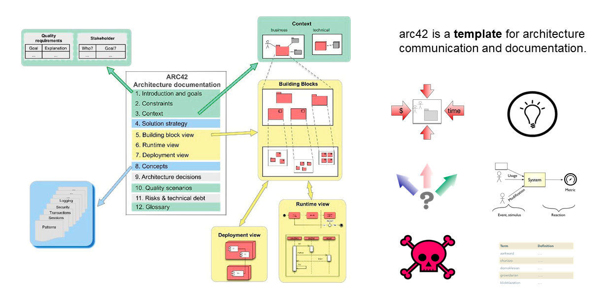
Strictly speaking, arc42 is not an architectural drawing method, but an architecture document template. Although diagram is a better choice than text in the architecture description as mentioned earlier, you still need to produce a relatively complete architecture document with both texts and diagrams. Arc42 is designed to help you better write architecture documents including the most important architecture diagram in the architecture documents. Multiple core chapters of arc42 introduction are related to the architecture diagram, and corresponding drawing methods are described in detail. Here I will not introduce the arc42 in detail, but briefly introduce similarities and differences of drawing methods between arc42 and C4 model.
Great ideas are always similar, and arc42 is no exception. The right part of the figure on the left summarizes several core chapters of arc42 that related to drawing.
Therefore, in essence, drawing methods advocated in arc42 are equivalent to and compatible with those in C4 model, and they can be used together. In practice, we use arc42 as the architecture document framework, and C4 model for architecture drawing.
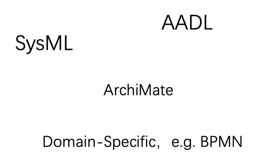
In addition to above methods, many other excellent architecture drawing methods have emerged during decades of vigorous development of the software industry. These methods include some universal methods such as SysML, AADL, ArchiMate, and some domain-specific methods such as BPMN commonly used in background business modeling scenarios of enterprises. If you are interested in these methods, please search and explore on your own.
So far, this chapter has introduced various methods of architecture drawing. However, in the actual process from methods to practices, there is still a crucial step. That is, what kind of tools should be selected for drawing? As the promoter of digital reform, programmers must fully use digital tools. I believe that everyone must have collected a lot of handy drawing tools in your daily work. Here, I only recommend two that I use the most.
It is better to teach people methodology than to introduce methods. Although the word "methodology" has been used widely in enterprises, it does have its value and meaning.
Methodology is the abstraction of methods in higher dimension, from which detailed methods for solving problems can be derived. Only after understanding the methodology, you can achieve a thorough understanding and master essential key points of solving problems. You will not be limited by a single specific method, because any method can be used quickly and flexibly, and you can get almost the same effect.
Therefore, in the last part of this article, I summarize various architecture drawing methods and try to extract a general architecture drawing methodology. I hope to help you better understand principles and ideas of architecture drawing. Even though those well-known methods and tools will eventually be out of date, you can still take it as the transition from old ones to new ones. In the past, there was UML; now we have C4 model, and what will there be in the future? However, this is not important, because even if those methods will be out of date, the methodology will not.
The question is what kind of core methodology is supporting those numerous methods? With "painstaking" efforts for nearly 15 seconds, I finally summed up the following set of methodology. Just kidding! Since it contains five interlocking points, just call it the five rings theory.
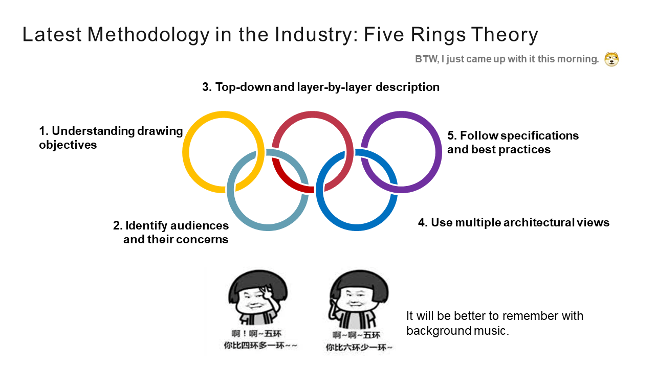
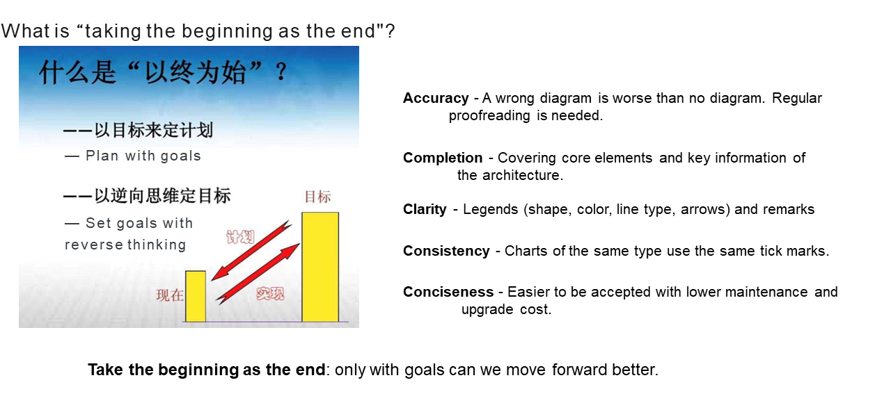
The first main point of architecture drawing is to have a deep understanding of drawing objectives. The so-called "take the beginning as the end" teaches us to move forward clearly only with the goal. Or otherwise, we may lose our way or even get the opposite result. Many of drawing objectives actually have been mentioned earlier. Here I'd like to give a brief summarization.
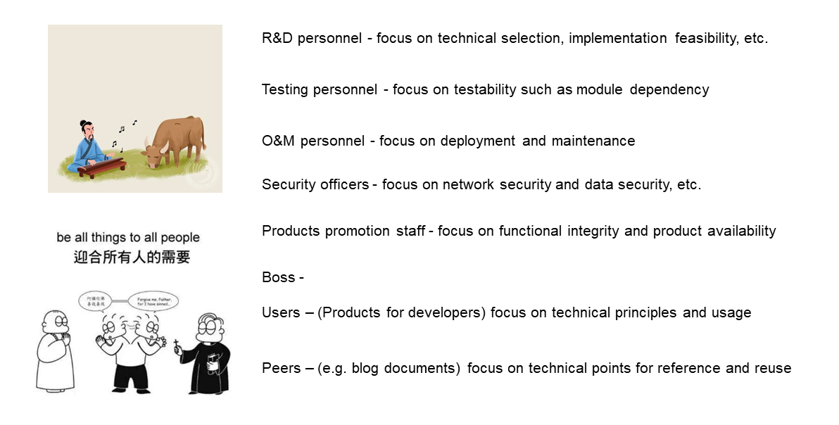
The second point of architecture drawing is to find out audiences and their concerns. If you can't find it, either the effect will be greatly reduced, or it will be hard for your audiences to understand. Some common audiences and concerns may include as follows.
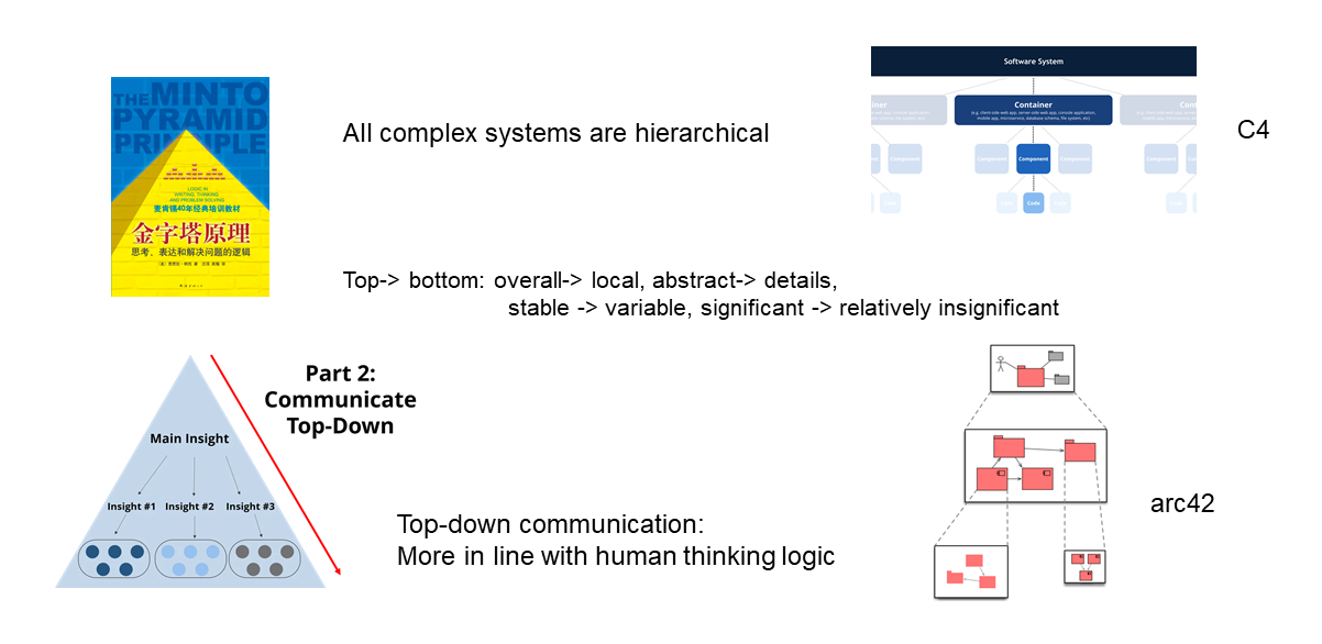
The third point of architecture drawing is top-down and layer-by-layer description through reasonable application of hierarchy. Whether it is C4 model or arc42 template, hierarchy is deeply applied and significantly emphasized. The reason is that it contains two universal principles.
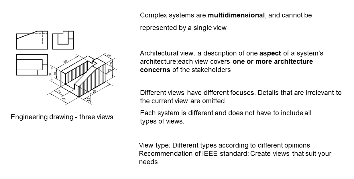
The fourth point of architecture drawing is similar to the traditional engineering drawing methodology, which refers to using multiple architectural views to describe the architecture. In engineering drawing, any three-dimensional products, from machine tools to parts, need to be described by at least three views: main view, top view and left view. As a reflection of the real world, the software system is also multi-dimensional, and it is impossible to cover all the key architecture information with only one view. Even if all this information is forcibly stuffed in one diagram, it will certainly be too complicated to be understood.
In the field of architecture design, architectural view has a special definition. It is a description of one aspect of a system's architecture, and each view covers one or more architecture concerns of the stakeholders. The above definition shows that different architecture views have different focuses. At the same time, other details unrelated to the current view are omitted when describing aspects you focus on. This is actually similar to divide-and-manage principle of hierarchical splitting. Architectural view is the dimension decomposition for the complete system, while the hierarchy is for a specific view to do top-down vertical drill-down. Both are orthogonal and can cooperate with each other. For example, the structure view, the deployment view, and even the dynamic view mentioned above can all be furtherly split in a hierarchical manner.
The fifth point in architecture drawing is an old saying, but it is a truth. Follow specifications and best practices. This point is no longer limited to architecture drawing, but has risen to the level of universal methodology in the field of engineering practice. As stated in the previous chapter, the goal of learning architecture drawing is to change it from a craft to an engineering. So, the drawing process of architecture certainly should conform to the engineering thinking.
On the one hand, drawing needs to follow clear specifications, and conduct constraint and guidance on the theoretical level. Thus, the high quality and standardization of processes and products can be ensured.
On the other hand, drawing also needs to follow best practices in the industry, continuously absorb excellent experience in practical level, and constantly improve drawing skills of ourselves and the team.
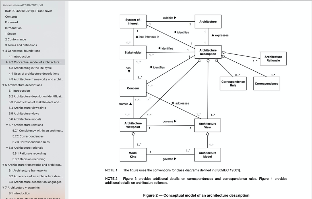
In fact, special standards, such as ISO, IEC, IEEE 42010:2011, have been established for the architecture description internationally. Many concepts of these standards are mentioned in this article, including stakeholder, concern, view, and viewpoint.
The Attraction of "Cloud-Native" to the Cloud Computing Ecosystem
Alibaba Cloud Launches New Enterprise Containers at KubeCon 2020

640 posts | 55 followers
FollowAlibaba Clouder - April 10, 2020
Alibaba Clouder - January 4, 2021
Alibaba Clouder - November 2, 2020
Alibaba Clouder - May 18, 2021
Alibaba Clouder - January 4, 2021
Alibaba Developer - January 29, 2021

640 posts | 55 followers
Follow Bastionhost
A unified, efficient, and secure platform that provides cloud-based O&M, access control, and operation audit.
Learn More Managed Service for Grafana
Managed Service for Grafana displays a large amount of data in real time to provide an overview of business and O&M monitoring.
Learn More Architecture and Structure Design
Customized infrastructure to ensure high availability, scalability and high-performance
Learn More DevOps Solution
Accelerate software development and delivery by integrating DevOps with the cloud
Learn MoreMore Posts by Alibaba Cloud Native Community