By Yen Sheng Tee, Alibaba Cloud Product Solutions Architect
Multi-attach disk allows you to attach a single shared block storage to multiple ECS instances within an availability zone. This allows the storage volumes to be accessed from multiple servers at the same time, making the application resilient to node failures to achieve high availability.
File Storage NAS provides a simple, scalable and shared file storage that works similarly for most applications. However, for customer who are running demanding enterprise applications (eg. clustered database, parallel file system) or specifically needing the ultra-low disk latency of EBS may opt for multi-attach EBS disk.
This article walkthrough the process of setting up multi-attach disk with GFS2 file system.
Traditionally, a file system manages storage retrieval between an operating system and storage system, but this can be made more complex when servers are organized into cluster. A cluster file system simultaneously mounts the file system on different servers so that it can be accessed and managed as one single logical system.
If you write data from multiple ECS instances without controlling the writes, the data may appear to be written correctly at first glance, but you may actually be destroying the file system. It is recommended to use a cluster file system after enabling multi-attach feature. Common cluster file systems include OCFS2, GFS2, Veritas CFS, Oracle ACFS and DBFS.
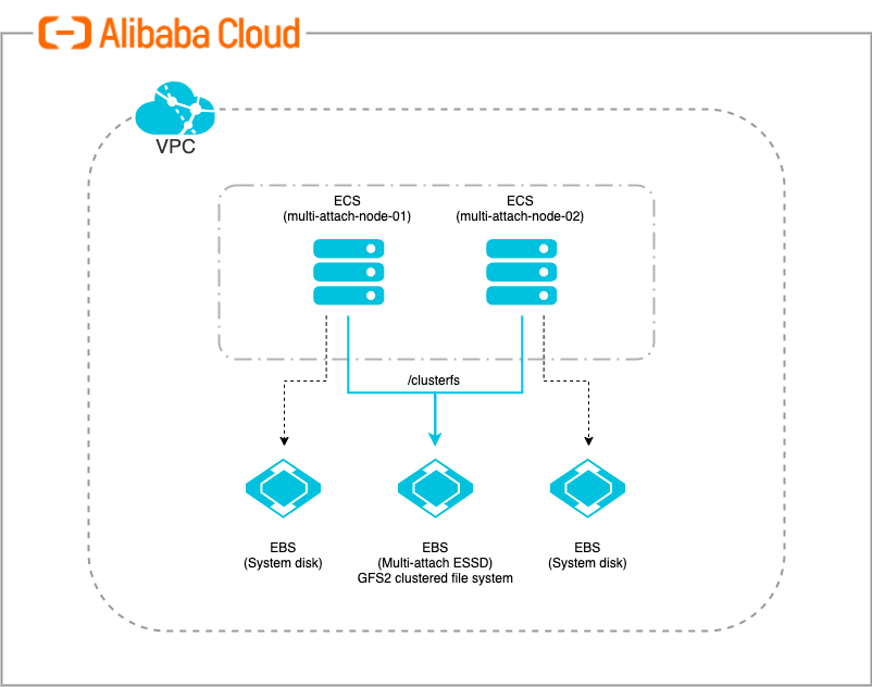
In this article, we will be setting up multi-attach EBS disk and use it across multiple ECS instances with GFS2 cluster file system configured. The setup consists of the following:
1. Create 2 ECS instances that support multi-attach EBS disk from Alibaba Cloud console.
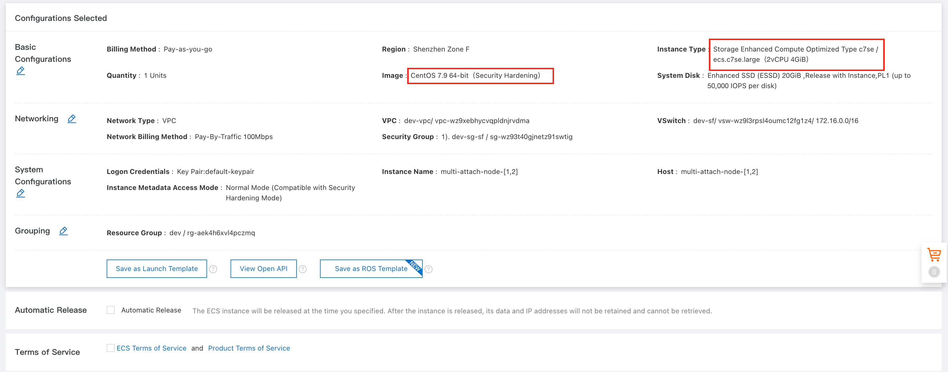
Node 1: multi-attach-node-01
Node 2: multi-attach-node-02
NOTE: Please take note that only specific ECS instance families support multi-attach disk. Refer to the Alibaba Cloud’s official documentation for more details.
2. Ports opening are required for the clustering software (eg. pcs, pacemaker), make sure all the ports are properly configured within your firewall, Network ACL or security group before proceeding.
NOTE: Please refer to Red Hat’s official documentation for all the port details.
1. Create a ESSD disk from Alibaba Cloud console, make sure "Multi-attach" is selected.
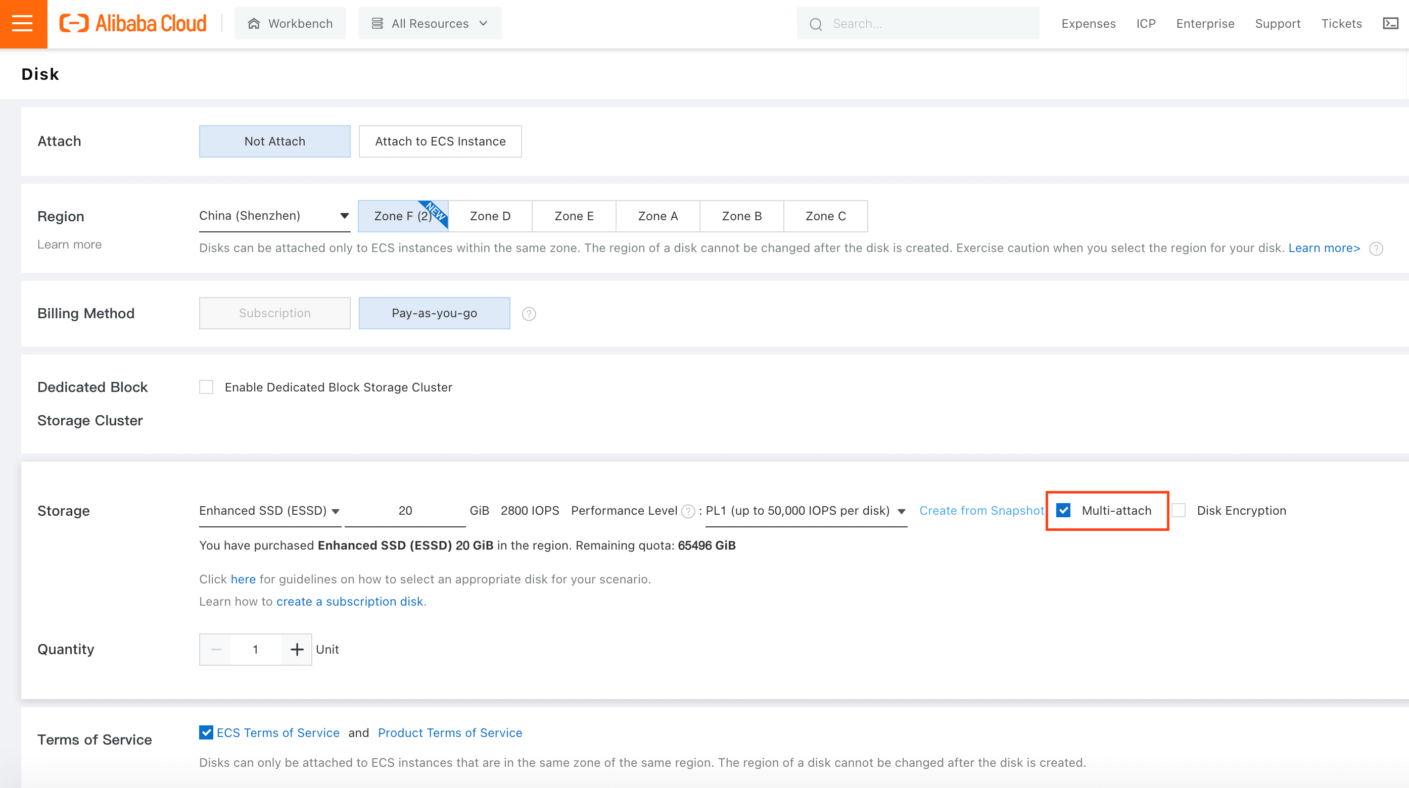
NOTE: Please take note that only specific region/zone support multi-attach enabled ESSD disk. Refer to Alibaba Cloud’s official documentation for more details.
2. Attach the disk to the 2 newly created ECS instances manually.
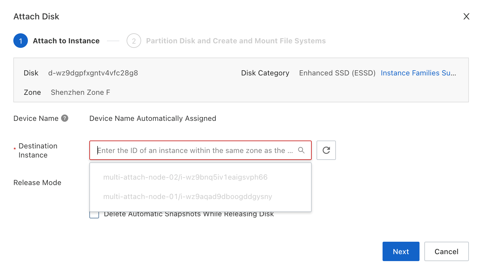
3. Make sure the disk is attached to both the ECS instances before proceeding.
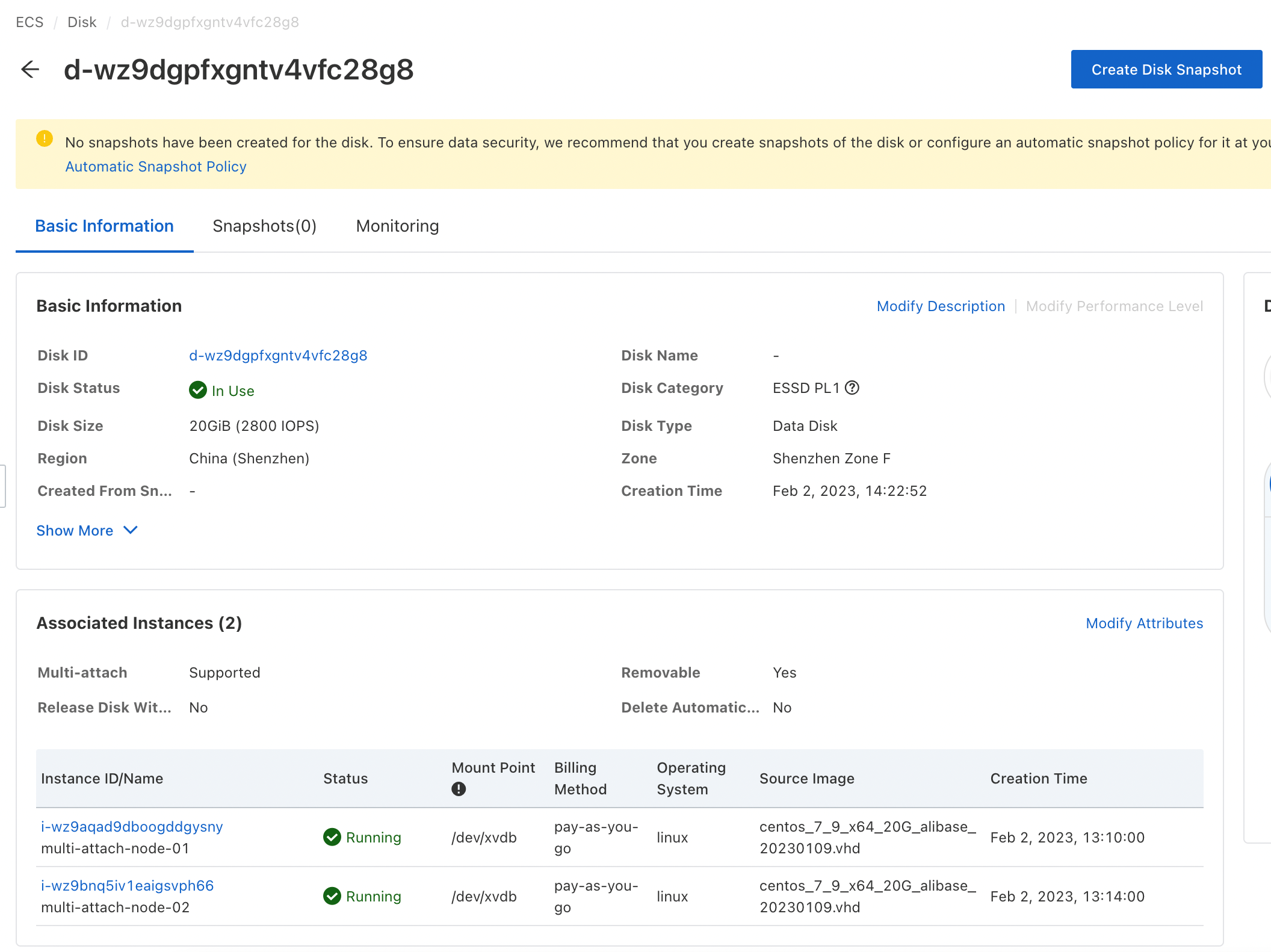
4. Login to the 2 ECS instances to validate the disk is properly attached to the instances.
# lsblk

5. Make sure both the ECS instances can communicate with each other using hostname. Modify the /etc/hosts file accordingly if required.

RHEL Pacemaker is a cluster software that provide the basic functions for a group of computers known as nodes to work together as a cluster. Once the cluster is formed, we can set up a cluster for sharing files on GFS2 file system.
1. Install cluster software packages on both the ECS nodes of the cluster.
# yum -y install pcs pacemaker2. The cluster software will create a pcs administration account ID "hacluster" to configure the cluster and communicate among all the cluster nodes. You must set a password on each node for the user ID "hacluster". It is recommended that the password for user "hacluster" be the same on each node.
# passwd hacluster
3. Enable and start the pcs daemon services. Perform this for both the nodes.
# systemctl enable pcsd.service
# systemctl start pcsd.service
4. Use pcs cluster command to authenticate the pcs user "hacluster" for each node in the cluster. The following command authenticates user "hacluster" on multi-attach-node-01 for both of the nodes in a two-node cluster (multi-attach-node-01 and multi-attach-node-02). Perform this on one of the nodes.
# pcs cluster auth <node-1> <node-2>
Double check your instances connectivity, firewall, network ACL or security group in case you are getting timeout when performing the authentication. Proceed if you are getting "Authorized" for both the nodes.
5. Creating the cluster. The following command is creating a Cluster "hacluster" using 2 nodes (multi-attach-node-01 and multi-attach-node-02). Perform this on one of the nodes.
# pcs cluster setup --name <cluster-name> <node-1> <node-2>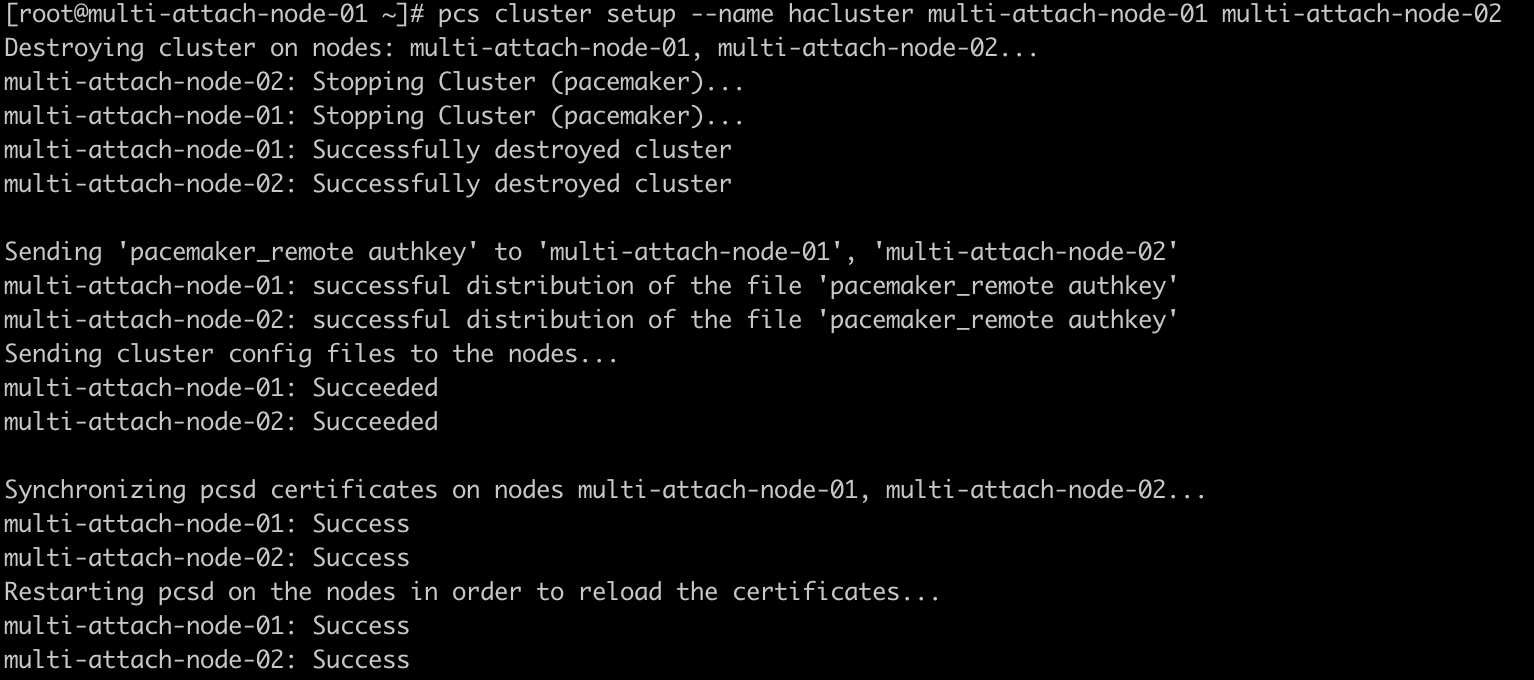
NOTE: Please take note on the cluster name. It is needed when you create the GFS2 file system later.
6. Start the cluster after the cluster has been setup successfully. Perform this on one of the nodes.
# pcs cluster start --all
7. Enable the cluster to auto-start after server reboot. Perform this on one of the nodes.
# pcs cluster enable --all
8. Check the status of the cluster setup. Perform this for both the nodes.
# pcs status corosync
# pcs status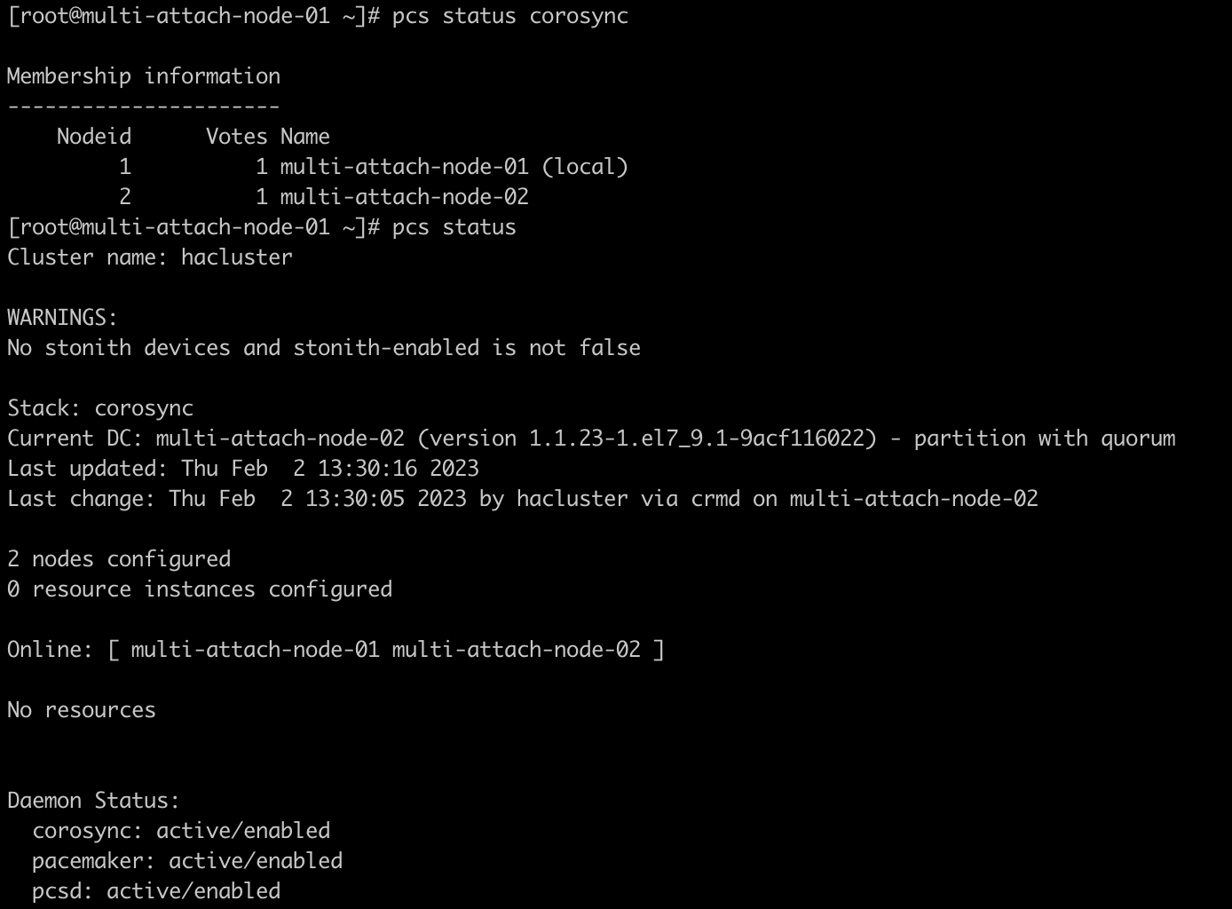
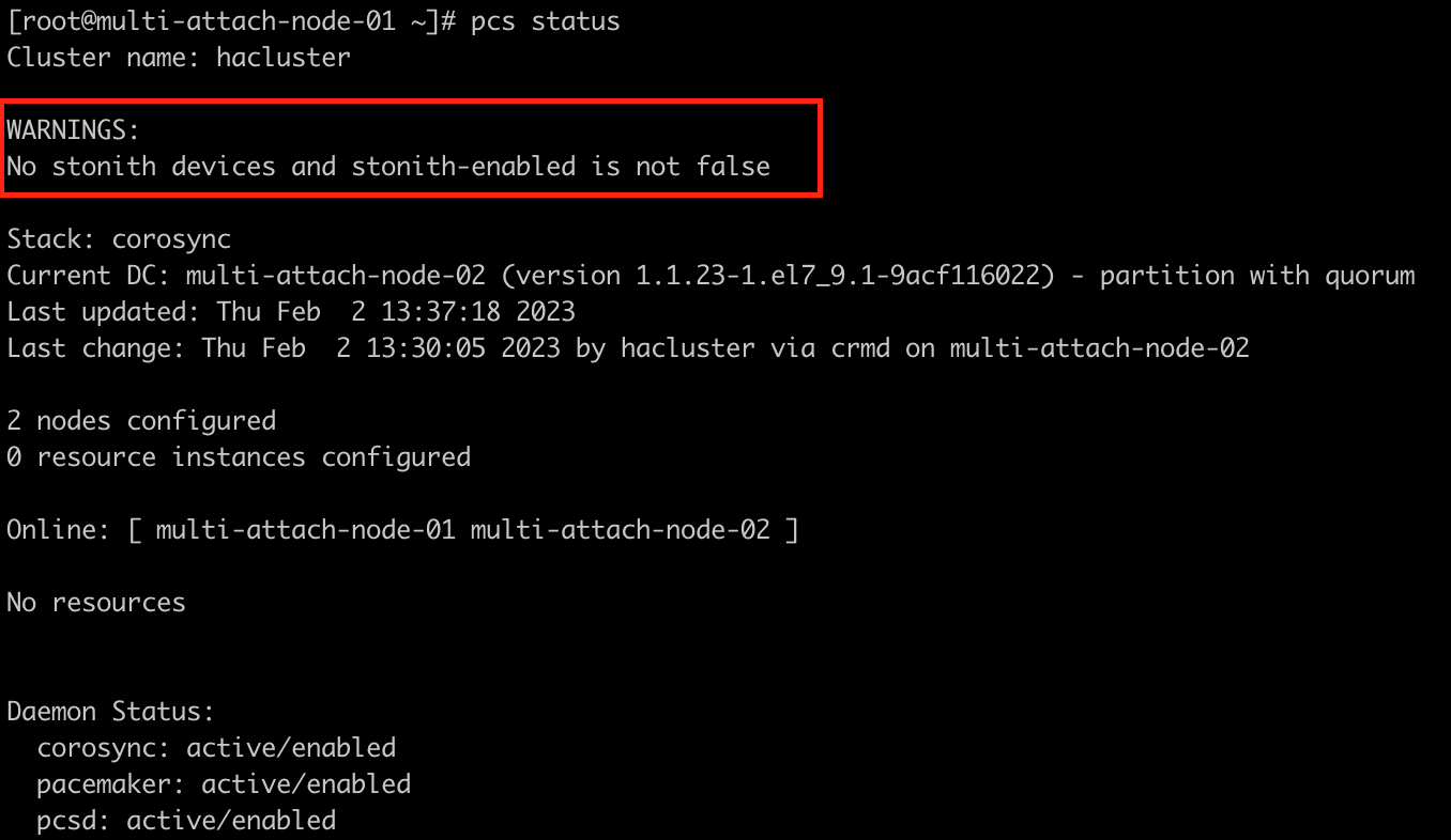
You might notice that there’s a warning on the previous cluster status, claiming that there’s no stonith devices and stonith is not enabled. STONITH stand for "Shoot The Other Node In The Head", it’s a mechanism used to protect your data from being corrupted by rogue nodes or concurrent access. It is a process used to prevent unnecessary I/O from nodes that failed or non-responsive but still have access to the shared disk. I/O fencing help isolate the impacted node from using the shared disk to avoid any data corruption.
1. Install fence_aliyun agent package on both the ECS nodes of the cluster.
# yum -y install fence-agents-aliyun2. Validate the fence agent is properly installed. Perform this for both the nodes.
# pcs stonith list
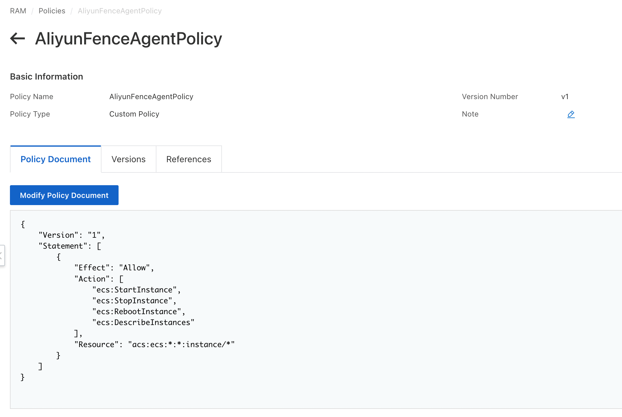
3. Create a new RAM policy, granting permission to start, stop, reboot and describe ECS instances. Following example grant the permissions to every single ECS instances. It is recommended to limit this to the specific ECS instances only.
{
    "Version": "1",
    "Statement": [
        {
            "Effect": "Allow",
            "Action": [
                "ecs:StartInstance",
                "ecs:StopInstance",
                "ecs:RebootInstance",
                "ecs:DescribeInstances"
            ],
            "Resource": "acs:ecs:*:*:instance/*"
        }
    ]
}
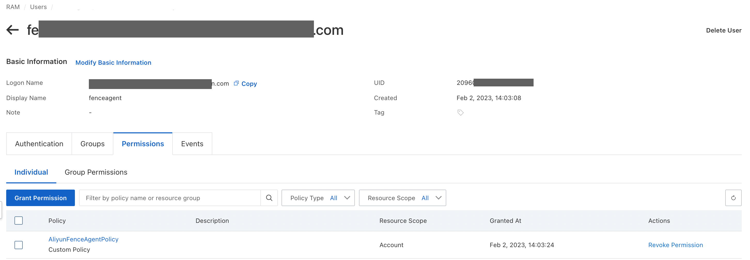
4. Create or re-use an existing RAM user created specifically for I/O fencing. This user will be used by the fence agent to manage the ECS instances.
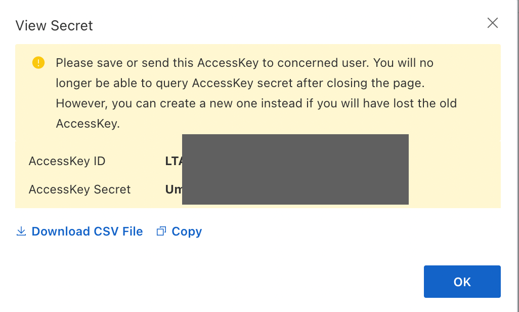
5. Create an access key for the newly created RAM user. Take note on the access key ID and secret for the next step.

6. Create and configure the fence agents. Perform this for both the nodes with different fence names.
# pcs stonith create <fence-name> fence_aliyun access_key="<access-key>" secret_key="<secret-key>" region="<region>" pcmk_host_map="<node1>:1;<node2>:2" pcmk_host_check="static-list" 

NOTE: You may configure other fencing parameters depending on your preferences. Refer to Pacemaker’s official documentation for more details.
7. Validate the I/O fencing status to make sure the fencing is configured properly. Perform this for both the nodes.
# pcs status
# pcs stonith show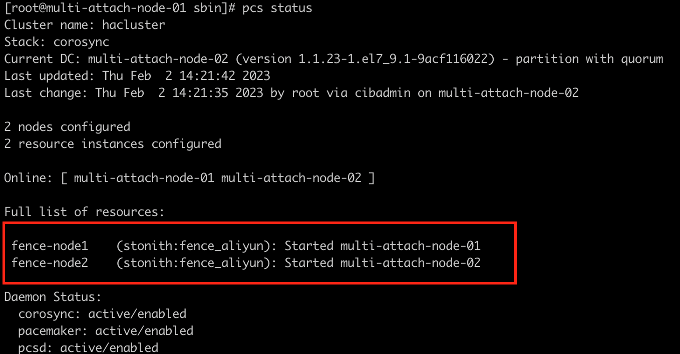

You have successfully configured the cluster software and setting up I/O fencing. Let’s continue to create the GFS2 file system and mount the disk.
1. Install gfs2-utils, lvm2-cluster and dlm packages on both the ECS nodes of the cluster.
# yum -y install gfs2-utils lvm2-cluster dlm 2. Update the pcs property of no-quorum-policy to freeze. This property is necessary because it means that cluster nodes will do nothing after losing quorum, and this is required for GFS2. If you would leave the default setting of stop, mounted GFS2 file system cannot use the cluster to properly stop, which will result in fencing of the entire cluster. Perform this for both the nodes.
# pcs property set no-quorum-policy=freeze3. Configure DLM resource. Perform this on one of the nodes.
The Distribute Block Manager, also known as controld is a mandatory part of the cluster. If, after starting, it fails a monitor test, then the nodes on which it fails need to be fenced, and that is to keep the cluster clean.
# pcs resource create dlm ocf:pacemaker:controld op monitor interval=30s on-fail=fence clone interleave=true ordered=true
# pcs status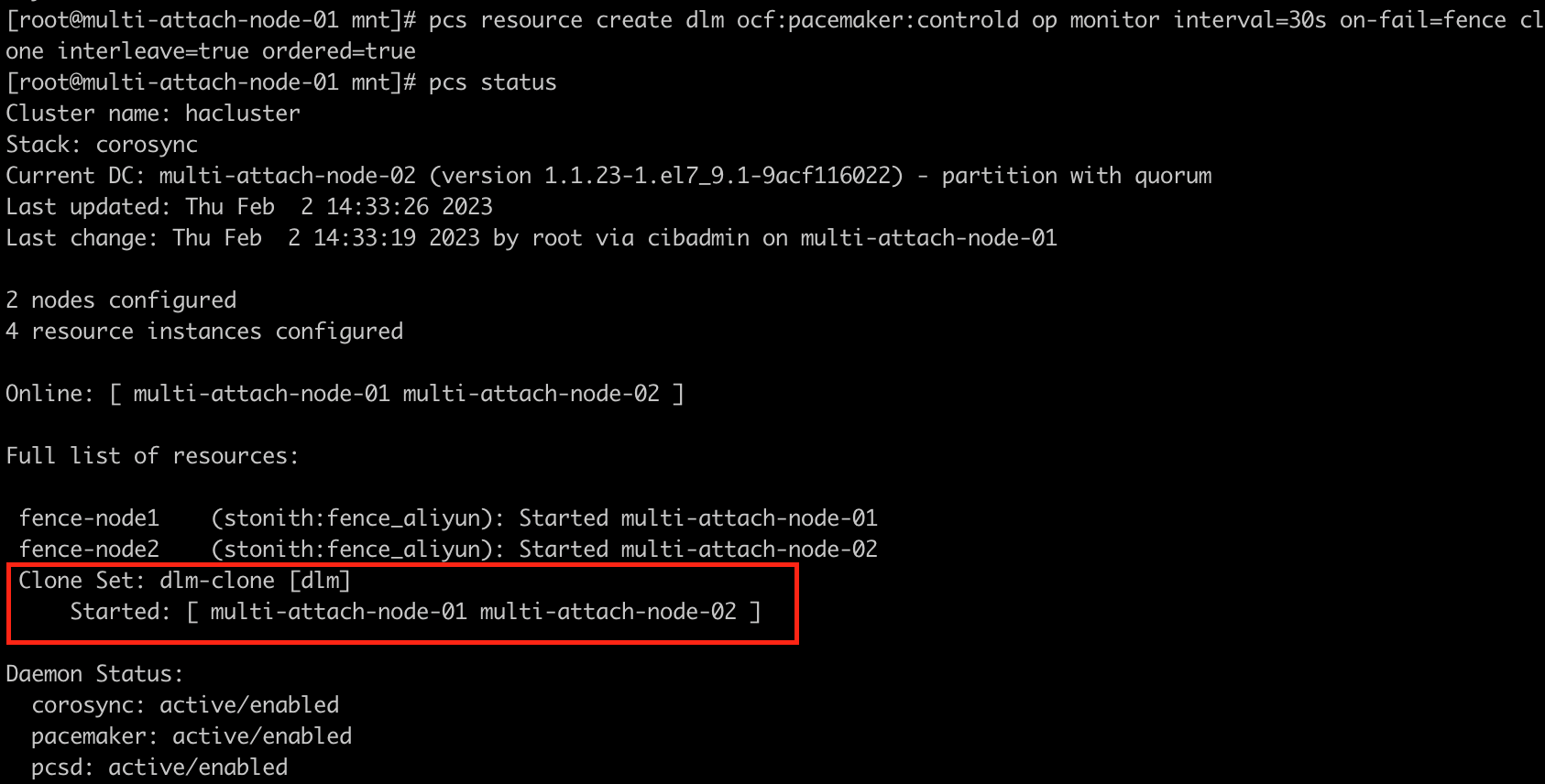
4. Configure CLVMD resource.
CLVMD is the clustered-locking service daemon that distributes LVM metadata updates across nodes of a cluster concurrently. If multiple nodes of the cluster require simultaneous read/write access to LVM volumes in an active/active system, then you must use CLVMD.
a) To enable clustered-locking, set locking_type=3 by executing following command. Perform this for both the nodes.
# lvmconf --enable-clusterb) Disable and stop lvm2-lvmetad service. Perform this for both the nodes.
# systemctl disable lvm2-lvmetad –nowc) Create CLVMD resource. Perform this on one of the nodes.
# pcs resource create clvmd ocf:heartbeat:clvm op monitor interval=30s on-fail=fence clone interleave=true ordered=trued) Validate the resource. Perform this for both the nodes.
# pcs status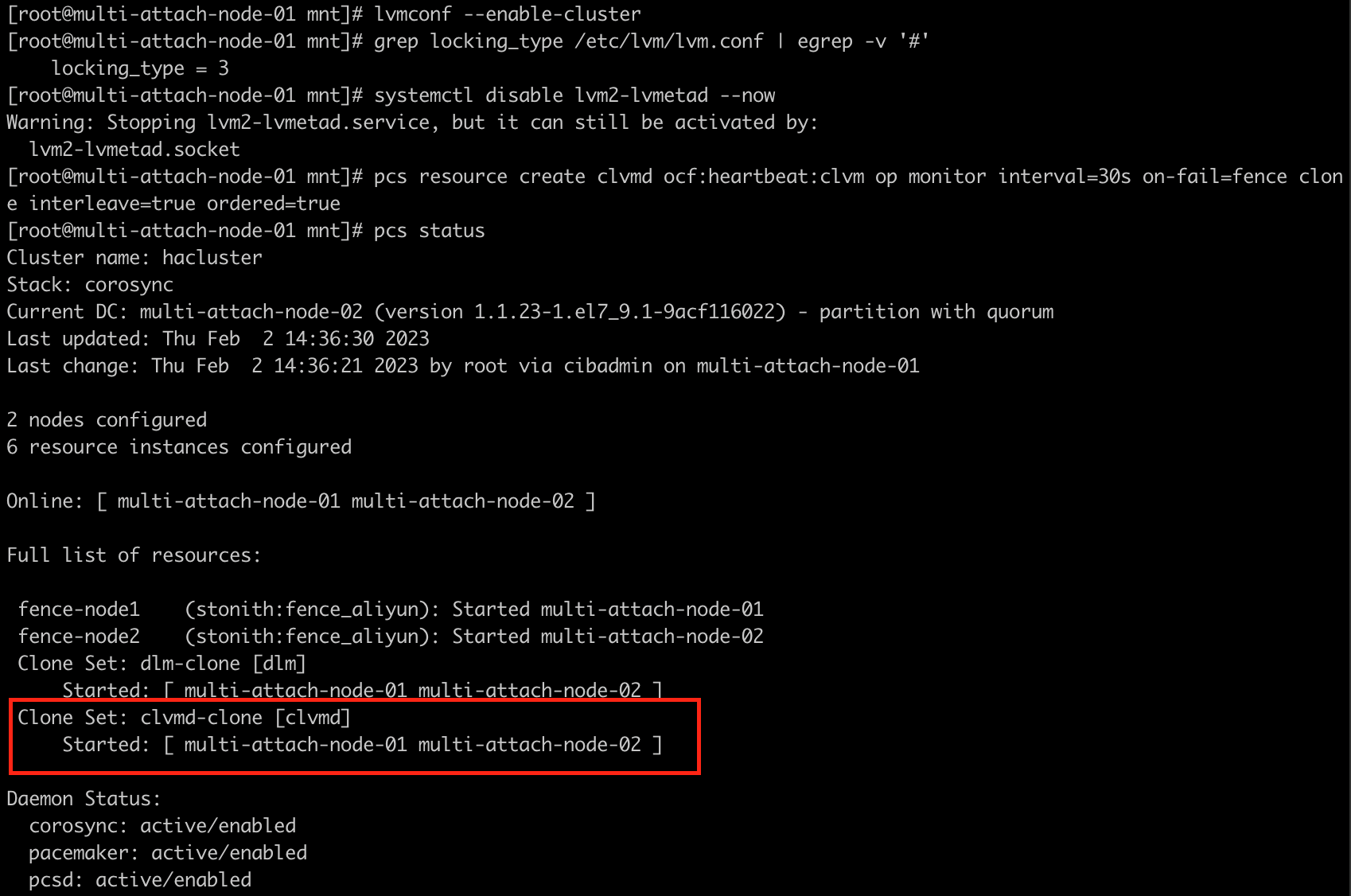
e) Change the resource start up order for DLM and CLVMD. Perform this on one of the nodes.
# pcs constraint order start dlm-clone then clvmd-clone
# pcs constraint colocation add clvmd-clone with dlm-clone
5. Set up shared storage on cluster nodes.
a) Identify the name of the newly mounted multi-attach ESSD shared disk.

b) Set up the logical volume on the cluster. The configuration will be synced automatically to all the other nodes.
# pvcreate <physical-volume-name>
# vgcreate -Ay -cy --shared <cluster-volume-group> <physical-volume-name>
# vgs
c) Create new logical volume using the shared volume group.
# lvcreate -l 100%FREE -n <logical-volume-name> <cluster-volume-group>
d) Create a GFS2 file system resource by using the new logical volume. Perform this on one of the nodes.
# mkfs.gfs2 -j3 -p lock_dlm -t <cluster-name>:<file-system-name> <logical-volume-path/logical-volume-name>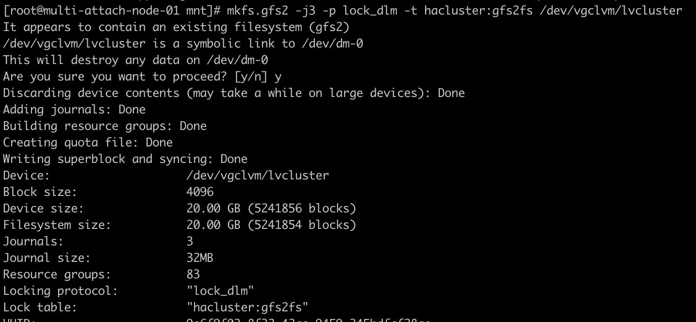
NOTE: Make sure you use the same cluster-name created earlier when configuring the cluster software.
6. Create a mount point for the shared file system on all the cluster nodes. Feel free to change this to any preferred path of your choice.
# mkdir /clusterfs7. Validate if the shared file system can be mounted properly.
# mount <logical-volume-path/logical-volume-name> <mount-point>
# mount | grep clusterfs
8. Create the cluster resource gfs2fs for the new GFS2 file system. Perform this on one of the nodes.
# pcs resource create <cluster-resource> Filesystem device="<logical-volume-path/logical-volume-name>" directory="<mount-point>" fstype=gfs2 options=noatime op monitor interval=10s on-fail=fence clone interleave=true
9. Validate the cluster status. Perform this for both the nodes.
# pcs status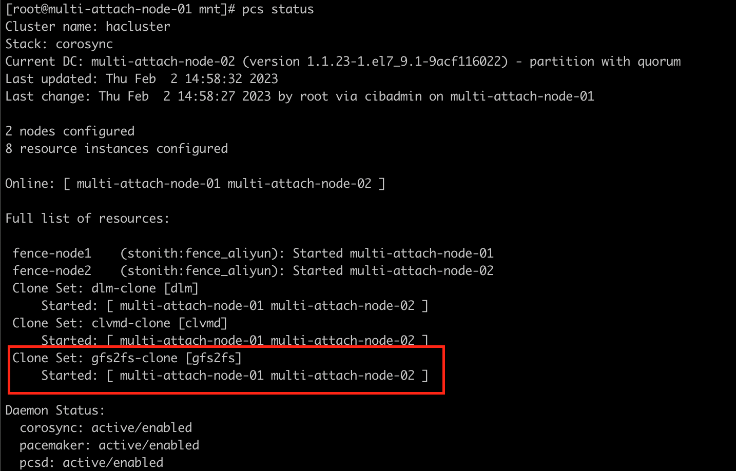
10. Change the resource start up order for CLVMD and GFS2. Perform this on one of the nodes.
# pcs constraint order start clvmd-clone then gfs2fs-clone
# pcs constraint colocation add gfs2fs-clone with clvmd-clone
11. Congratulation! You have successfully setup GFS2 clustered file system using the multi-attach ESSD disk. You may validate the GFS2 clustered file system by creating a file in one of the nodes. The file should be visible in the other cluster node.
Alibaba Cloud Community - February 10, 2023
Alibaba Cloud Community - April 24, 2022
Junho Lee - June 22, 2023
Junho Lee - June 15, 2023
Alibaba Cloud Community - August 16, 2023
Alibaba Cloud Community - April 24, 2022
 Elastic Block Storage
Block-level data storage attached to ECS instances to achieve high performance, low latency, and high reliability
Learn More Hybrid Cloud Distributed Storage
Provides scalable, distributed, and high-performance block storage and object storage services in a software-defined manner.
Learn More Storage Capacity Unit
Plan and optimize your storage budget with flexible storage services
Learn More Hybrid Cloud Storage
A cost-effective, efficient and easy-to-manage hybrid cloud storage solution.
Learn MoreMore Posts by Yen Sheng